Home Page
CUBE Page
INDEX
- Introduction
- MCU clocks
- How to use the CUBE for create a new project for STM32F4-Discovery
- Where to get this example ready to use for KEIL
- Glossary
INTRODUCTION
This explanation try to give you an introduction to the:
- MCU Clock
- How to configure MCU Clock using the CUBE.

Up to now CUBE support the below C Compiler:
- IAR
- KEIL
- ATOLLIC
- AC6 & GCC
More info regarding the principal C Compilers are here.
For test this example you need to use:
- CUBE - The CubeMx software is here at the end of the page.
- F4 Library (see at the end of the page)
- UM1725 User Manual Description of STM32F4xx HAL drivers
- Manual of: STM32F407VG
- STM32F4-Discovery
-
MCU clocks
The Clocks is a very important part of the configuration of your Cortex Mx.
All Cortex Mx have one or more internal oscillator (RC) and one or more external crystals oscillators (Xtal).
Crystal Oscillator
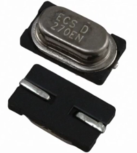
The external crystal oscillator must be chosen in according to the manual of the Cortex Mx that you use.We suggest you to read this manuals:
- AN2867 - Oscillator design guide for STM8S, STM8A and STM32 microcontrollers
- AN4661 - Getting started with STM32F74xxx/STM32F75xxx MCU hardware development
- AN4488 - Getting started with STM32F4xxxx MCU hardware development
- AN4206 - Getting started with STM32F3 series hardware development
- AN3320 - Getting started with STM32F20xxx/21xxx MCU hardware development
- AN2586 - Getting started with STM32F10xxx hardware development
- AN4080 - Getting started with STM32F0x1/x2/x8 hardware development
- AN4467 - Getting started with STM32L0xx hardware development
- AN3216 - Getting started with STM32L1xxx hardware development
- AN4555 - Getting started with STM32L4 series hardware development
Below there is a comparison from internal clock (RC) and external clock (crystal clock).
Internal RC clock at 16Mhz (suppose: 1%)
| Accuracy |
Error |
| 1% | 160000 Pulses/Seconds |
| 14.4 minutes/day |
External Crystal Clock at 16MHz (suppose: 100 ppm : parts per milion)
| Accuracy |
Error |
| 0,01% (100ppm) |
1600 Pulses/Seconds |
| 8.64 seconds/day |
External Crystal Clock at 16MHz (suppose: 10 ppm : parts per milion)
| Accuracy |
Error |
| 0,001% (10ppm) |
160 Pulses/Seconds |
| 0.864 seconds/day |
The top of external crystal oscillator are:
TCXO (Temperature Compensate Xtal Oscillator)
OCXO (Oven Controlled Xtal Oscillator)
OCXO (Oven Controlled Xtal Oscillator)
For high speed serial communication (Ethernet) is a must use Xtal from 0.1 to max 1 ppm.
Normally the Xtal (for STM32) is in the range from 4 to 26 MHz and for reach the max MCU frequency is a must to use the internal PLL (phase looked loop).
The PLL multiply the Xtal frequency in order to reach the desired max MCU frequency.
Now, for explain, in a real application, how to configure the clocks we use the STM32F4-Discovery.
Please download the manual of STM32F407VG that is the name of the Cortex M4 used in the discovery board.
If you look at pg.18 you see the internal configuration of the STM32F407.
From pg.18 you can see:
- The core clock is 168 Mhz (SYSCLK)
- The AHB1, AHB2, AHB/APB1 and AHB/APB2 bus are 168Mhz
- The APB2 is 84MHz
- The APB1 is 42MHz
- AMBA == Advanced Microcontroller Bus Architetture
- AHB == Advanced High-Performance Bus
- APB == Advanced Peripheral Bus

Before the release of CUBE, for configure the clock of STM32 was necessary spend a long time to configure the RCC functions.
Now for configure the clock tree I suggest to use the CUBE. See the below, the clocks configuration page.

-
How to use the CUBE for create a new project for STM32F4-Discovery
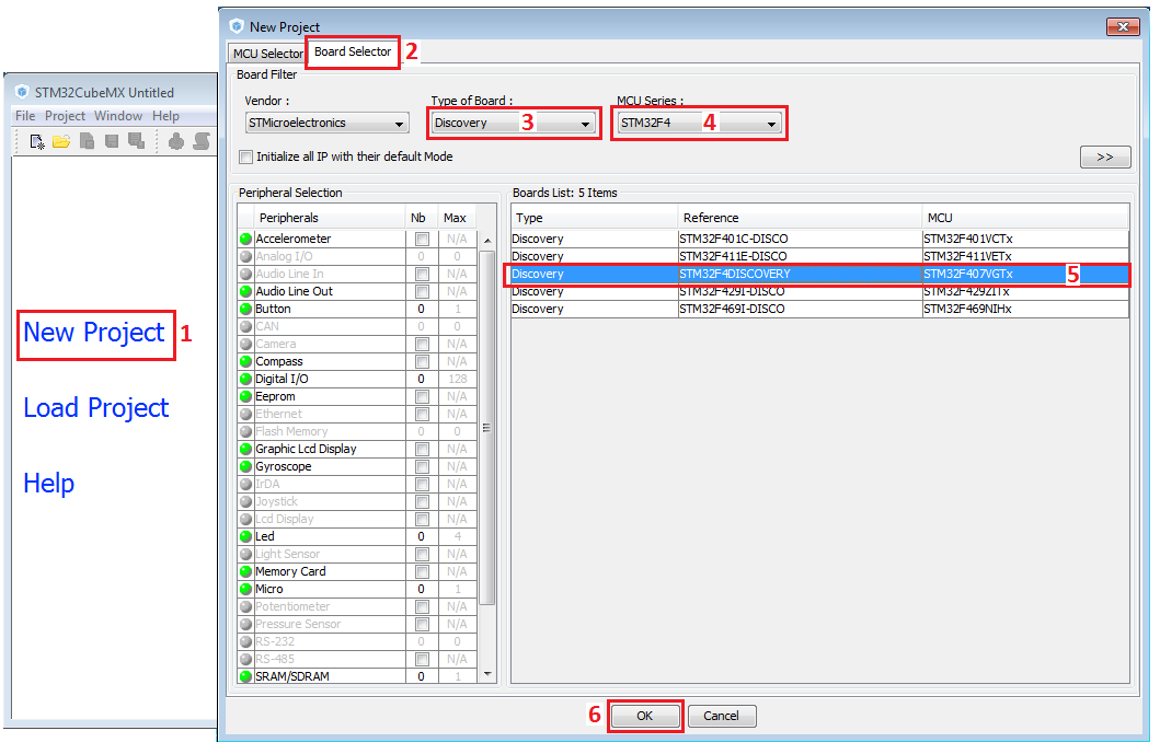
We decide to use the STM32F4-Discovery for this tutorial.
For create a new project we decide to use CUBE and the predefined SetUp that STM has already done for the STM32F4-Discovery.
By the CUBE is possible configure all the clock source and the internal MCU clock in graphics mode.
Follow the steps shown below.
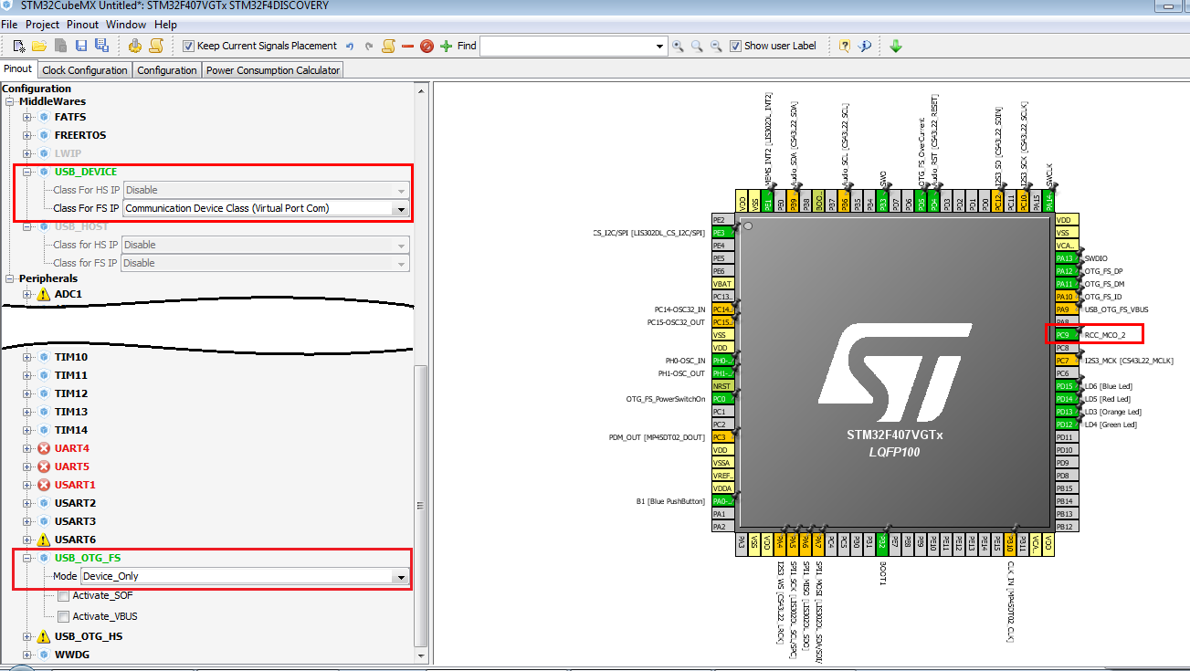
For a future application we decide to select the USB device and the VirtualCom, see below.
For see if, our clock configuration is correct, we decide to enable the RCC_MCO_2, see the PC9 below.
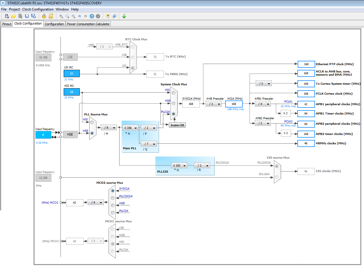
Now select the: Clock Configuration page
and check that your configuration, is the same as shown below.
NOTE:
Now is a time to choose what C compiler you want to use and the working directory.
For do this follow the steps below.
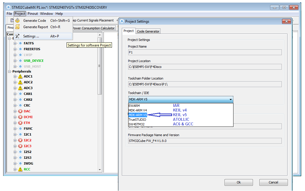
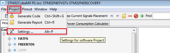
Select: Project and Settings... (see below).
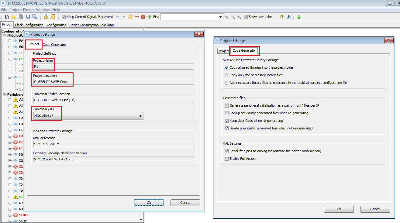
Now, from the page that appear, select a Project Location, a Project Name, and the compiler that you want to use (Toolchain/IDE).
Next, select: Code Generator
and do the same configuration that you see below.
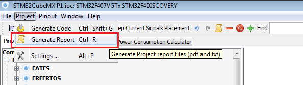
Now, select: Project and Generate Report
After this, you will have a pdf file that contain all the configuration of your project, MCU name, Pins allocation, etc.
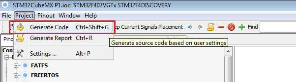
Now it is time to generate the code, select: Project and Generate Code
After this, you will have a complete project ready to use.
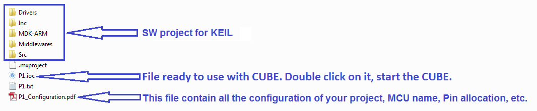
After the actions explained before, you have in your working directory something like below.
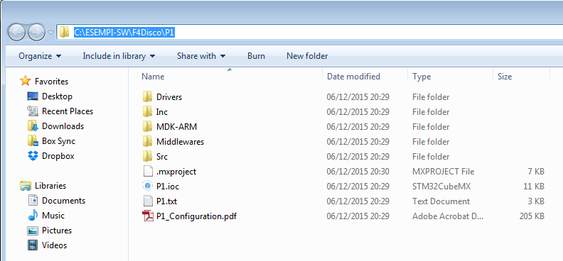
For compile the program, enter in the directory: MDK-ARM
and double click on: P1.uvprojx

ATTENTION:

Now compile your program and you must see:
0 Error(s), 0 Warning(s)
See below.

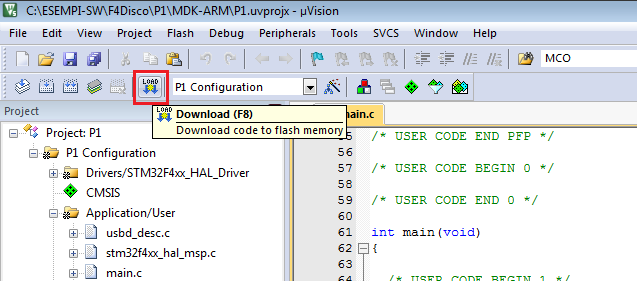
It is time to download your program on STM32F4-Discovery, see below.
Now if you connect an oscilloscope to PC9 (MCO2) you must see 42MHz, this means that your SYSCLK is configure to 168Mhz, see below the MCO2 configuration .
Now it is time to flash a LED, for do this follow the steps below.
Open the main.c and insert the lines of code shown below.

Compile and download again, your program on STM32F4-Discovery. At this point you must see Blue LED blinking.
The docs regarding F4 HAL librry functions is here:
UM1725 User Manual Description of STM32F4xx HAL drivers
In the above manual you can find:
How to use the CUBE for create a new project for STM32F4-Discovery
We decide to use the STM32F4-Discovery for this tutorial.
For create a new project we decide to use CUBE and the predefined SetUp that STM has already done for the STM32F4-Discovery.
By the CUBE is possible configure all the clock source and the internal MCU clock in graphics mode.
Follow the steps shown below.
For a future application we decide to select the USB device and the VirtualCom, see below.
For see if, our clock configuration is correct, we decide to enable the RCC_MCO_2, see the PC9 below.
Now select the: Clock Configuration page
and check that your configuration, is the same as shown below.
NOTE:
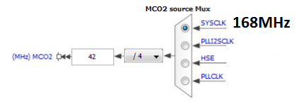
We selected the MCO2 with SYSCLK input and the output is divided by 4.
In this way we reach 42MHz on the MCO2 pin (PC9).
We choose 42Mhz because our oscilloscope has 100MHz bandwidth. In this way we have a good resolution on our oscilloscope.
In this way we reach 42MHz on the MCO2 pin (PC9).
We choose 42Mhz because our oscilloscope has 100MHz bandwidth. In this way we have a good resolution on our oscilloscope.
Now is a time to choose what C compiler you want to use and the working directory.
For do this follow the steps below.
Select: Project and Settings... (see below).
Now, from the page that appear, select a Project Location, a Project Name, and the compiler that you want to use (Toolchain/IDE).
Next, select: Code Generator
and do the same configuration that you see below.
Now, select: Project and Generate Report
After this, you will have a pdf file that contain all the configuration of your project, MCU name, Pins allocation, etc.
Now it is time to generate the code, select: Project and Generate Code
After this, you will have a complete project ready to use.
After the actions explained before, you have in your working directory something like below.
P1.ioc is the CUBE configuration
P1_Configuration.pdf contain all the configuration of your project, MCU name, Pin allocation, etc.
MDK-ARM contain the KEIL files configuration (this because we decide to use KEIL).
P1_Configuration.pdf contain all the configuration of your project, MCU name, Pin allocation, etc.
MDK-ARM contain the KEIL files configuration (this because we decide to use KEIL).
For compile the program, enter in the directory: MDK-ARM
and double click on: P1.uvprojx
ATTENTION:
Before to compile is necessary do some configurations that are shown below, follow the steps from 1 to 10.
Now compile your program and you must see:
0 Error(s), 0 Warning(s)
See below.
It is time to download your program on STM32F4-Discovery, see below.
Now if you connect an oscilloscope to PC9 (MCO2) you must see 42MHz, this means that your SYSCLK is configure to 168Mhz, see below the MCO2 configuration .
Now it is time to flash a LED, for do this follow the steps below.
Open the main.c and insert the lines of code shown below.
Compile and download again, your program on STM32F4-Discovery. At this point you must see Blue LED blinking.
The docs regarding F4 HAL librry functions is here:
UM1725 User Manual Description of STM32F4xx HAL drivers
In the above manual you can find:
HAL_GPIO_TogglePin
HAL_Delay
HAL_Delay