

Link
Introduction
Software libraries and demonstration applications
Kit setup
Running the STM32W108xx kits
Network analyzer Perytons
Link
Introduction
The STM32W108B-SK and STM32W-EXT, starter and extension kits are easy to use tools for the STM32W108xx microcontrollers.
This family of microcontrollers integrates a 32-bit ARM® Cortex-M3 microprocessor and a 2.4 GHz, IEEE 802.15.4-compliant transceiver. The kits demonstrate how effectively the STM32W108xx can be used in real IEEE 802.15.4 applications.
They are suitable for different types of wireless network scenarios such as:
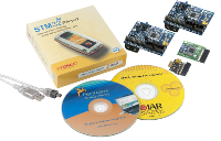
The STM32W108B-SK starter kit package contains the following hardware components:
The STM32W108B-SK (starter kit package) contains the following software components:
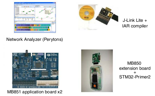
One CD-ROM including Perytons network analyzer (V3.05 or later).
One CD-ROM including the IAR Limited 30-days Evaluation Compiler 5.40.7 or later.
One CD-ROM including the Raisonance Development Suite for the STM32-Primer2.
The STM32W-EXT (extension kit package) contains:
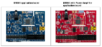
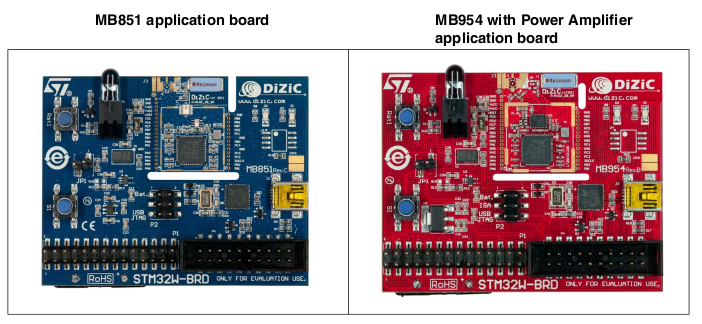
Two STM32W108 application boards (MB851)
Two STM32W108 application boards with a power amplifier (MB954).
This family of microcontrollers integrates a 32-bit ARM® Cortex-M3 microprocessor and a 2.4 GHz, IEEE 802.15.4-compliant transceiver. The kits demonstrate how effectively the STM32W108xx can be used in real IEEE 802.15.4 applications.
They are suitable for different types of wireless network scenarios such as:
- Mesh networks (based on the ZigBee PRO protocol stack) typically used in home automation and smart energy applications.
- Remote control and target networks (based on the ZigBee RF4CE protocol stack) used for driving consumer devices such as TVs, set-top boxes, etc.
- Point to point networks (based on a Simplified MAC library) used to address a basic IEEE 802.15.4 communication.
This configuration enables customers to develop any protocol stack of their choice.
The STM32W108B-SK starter kit package contains the following hardware components:
Two STM32W108 application boards (MB851)
One STM32W108 extension board (MB850)
One Raisonance STM32-Primer2 tool (STM3210E-PRIMER)
One J-Link Lite JTAG Flash programmer and debugger
One mini USB cable
Four AAA batteries
One STM32W108 extension board (MB850)
One Raisonance STM32-Primer2 tool (STM3210E-PRIMER)
One J-Link Lite JTAG Flash programmer and debugger
One mini USB cable
Four AAA batteries
The STM32W108B-SK (starter kit package) contains the following software components:
One CD-ROM including Perytons network analyzer (V3.05 or later).
One CD-ROM including the IAR Limited 30-days Evaluation Compiler 5.40.7 or later.
One CD-ROM including the Raisonance Development Suite for the STM32-Primer2.
The STM32W-EXT (extension kit package) contains:
Two STM32W108 application boards (MB851)
Two STM32W108 application boards with a power amplifier (MB954).
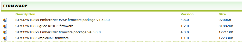
Software libraries and demonstration applications
The following SW are available on the STM32W 32-bit RF microcontroller webpages at www.st.com/stm32w, inside the page select Design Resources.
For
a detailed description of each software and documentation tree, refer
to the related documentation (starting from the HTML index file, that
comes with each installer file).
Note:
Note:
Each SW also provides a set of prebuilt binary images (applications and utilities).
All the examples are configured for IAR.
All the examples are configured for IAR.
Kit setup
Powering on the boards
Each application board can be powered as follows:
Via batteries (fit 1-2 on the P2 jumper)
Via USB or JTAG (fit 5-6 on the P2 jumper)
Via USB or JTAG (fit 5-6 on the P2 jumper)
Note:
The jumper position 3-4 is reserved for internal usage.
To enable the application board temperature, MEMS and infrared sensors, fit jumper JP1.
To enable the application board temperature, MEMS and infrared sensors, fit jumper JP1.
The MB850 extension board is designed as an IEEE 802.15.4 application-specific daughterboard.
It must be connected to the STM32-Primer2 extension connector to be powered through the STM32-Primer2.
Installing drivers for USB virtual COM
In
order to use the serial communication channel on an application board,
a driver for the FTDI USB<-> Serial converter or a Virtual COM
port driver for an STM32F103xx must be installed.
The correct driver to install is based on the application board revision number.
The following application boards requires the driver FTDI USB <-> Serial converter:
MB851 Rev A
MB851 Rev B
MB954 Rev A
The related drivers can be downloaded from the FTDI website at: www.ftdichip.com/Drivers/D2XX.htm
All other application boards require the STMicroelectronics Virtual COM port driver which can be directly downloaded from here.
Setting up the application serial communication channel
To
get full access to all the available commands, some demonstration
applications may require that the application board is interfaced with
the user through a serial communication channel (virtual COM through
USB).
To set a serial communication channel for the application board, follow these steps:
To set a serial communication channel for the application board, follow these steps:
1) Fit the application board jumper P2 on position 5-6 (power via USB).
2) Connect a mini USB cable to the application board mini-USB connector and to a PC USB port.
3) Right-click on My Computer, select Manage, Device Manager, and open Ports (COM & LPT) to display the related USB COMx port.
4) Open a hyper terminal on the corresponding USB virtual COMx port with the following configuration:
The STM32-Primer2 and MB850
demonstration applications use the STM32-Primer2 resources (LCD,
joystick with button, touch screen display) as I/O communication
channels.2) Connect a mini USB cable to the application board mini-USB connector and to a PC USB port.
3) Right-click on My Computer, select Manage, Device Manager, and open Ports (COM & LPT) to display the related USB COMx port.
4) Open a hyper terminal on the corresponding USB virtual COMx port with the following configuration:
– Bit rate: 115200
– Data bits: 8
– Parity: None
– Stop bits: 1
– Flow control: None
– Data bits: 8
– Parity: None
– Stop bits: 1
– Flow control: None
Running the STM32W108xx kits
STM32W108B-SK (starter kit package)
STM32W-EXT (extension kit package)
Run preloaded ZigBee PRO sink application
Insert the MB850 inside the STM32-Primer2.
On the STM32-Primer2 there are applications preloaded that are:
- ZigBee PRO sink application
- ZigBee RF4CE RC application
- Simple MAC sun sample application
There is one MB851 with preloaded:
- ZigBee PRO sensor firmware (application board labeled as “Sensor”)
There is one MB851 with preloaded:
- Perytons capture firmware (application board labeled as “Analyzer”)
This allows you to immediately run the ZigBee PRO SINK, SENSOR demonstration applications, just by selecting the sink application on the STM32-Primer2 (see Section: ZigBee PRO SINK SENSOR for more details).
You can also start a packet capture session using the Perytons analyzer (see Section: Network analyzer for more details).
STM32W-EXT (extension kit package)
In
the STM32W-EXT extension kit, all four boards are preprogrammed with
EmberZNet ZigBee PRO sensor firmware (application board labeled as “Sensor”).
Using these boards, you can extend the sink, sensor mesh network with other four sensor nodes.
Using these boards, you can extend the sink, sensor mesh network with other four sensor nodes.
Run preloaded ZigBee PRO sink application
SetUp STM32-Primer2
Now press the joystick on the STM32-Primer2 and select: Permit join
Immediately press the S1 button on the MB851 labeled "Sensor"
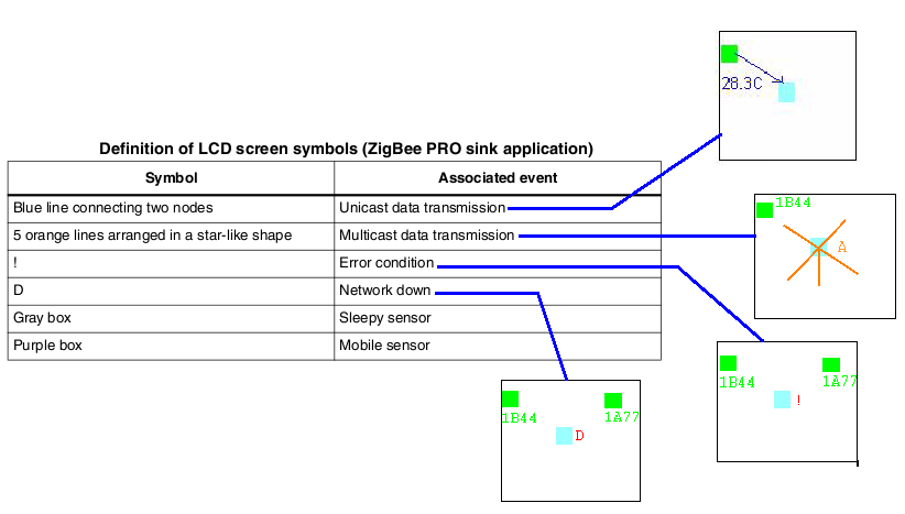
At this point you must see (on the display of STM32-Primer2) something like this.
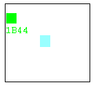
Possible screens that can be seen (see below).
At this point if you turn off
the MB851 labeled "Sensor", after about 40 seconds, the green node icon
will disappear from the display of the STM32-Primer2.
If you turn on the MB851 labeled "Sensor", after about 20 seconds, the green node icon will reappear on the STM32-Primer2.
The configuration is stored in the MB851 labeled "Sensor" and in the STM32-Primer2, this means that if you turn off both and then turn on again (remember that on STM32-Primer2 is necessary run the application: ZP SINK) the network is automatically restored in about 20 seconds.
For more detail concerning ZigBee PRO sink application see the manual:
The STM32-Primer2 tool is delivered with the sink application preloaded. This application automatically configures the connected MB850 extension board with the related ZigBee PRO sink application.
To run the ZigBee PRO sink application on the STM32 Primer2 and MB850 boards, follow these steps:
SetUp MB851 labeled "Sensor"To run the ZigBee PRO sink application on the STM32 Primer2 and MB850 boards, follow these steps:
1. Connect the MB850 to the extension connector of the STM32-Primer2 tool.
2. Power on your STM32-Primer2.
3. Press the joystick button to launch the main menu and select Applic.->ZP SINK
2. Power on your STM32-Primer2.
3. Press the joystick button to launch the main menu and select Applic.->ZP SINK
Follow this steps:
1. Insert the batteries
2. move jumper P2 to BAT position
2. move jumper P2 to BAT position
Now press the joystick on the STM32-Primer2 and select: Permit join
Immediately press the S1 button on the MB851 labeled "Sensor"
At this point you must see (on the display of STM32-Primer2) something like this.
Possible screens that can be seen (see below).
If you turn on the MB851 labeled "Sensor", after about 20 seconds, the green node icon will reappear on the STM32-Primer2.
The configuration is stored in the MB851 labeled "Sensor" and in the STM32-Primer2, this means that if you turn off both and then turn on again (remember that on STM32-Primer2 is necessary run the application: ZP SINK) the network is automatically restored in about 20 seconds.
For more detail concerning ZigBee PRO sink application see the manual:
UM0894 (User Manual - STM32W-SK and STM32W-EXT starter and extension kits for STM32W108xx microcontrollers) that is here.
Network analyzer Perytons
To install the Perytons network analyzer, insert the related CD-ROM and follow the installation instructions.
To use the Perytons network analyzer, follow these steps:
An example of the possibility of Perytons SW is here.
To use the Perytons network analyzer, follow these steps:
1. Application board (MB851) labeled as “Analyzer“: fit jumper P2 on position 5-6 (power via USB) and connect to a PC USB port.
2. Open the Perytons tool (from Start, Programs).
3. For instructions about how to start a packet capture session refer to the documentation on the Perytons CD-ROM.
When a packet capture session is ongoing, the application board LEDs behave as follows:2. Open the Perytons tool (from Start, Programs).
3. For instructions about how to start a packet capture session refer to the documentation on the Perytons CD-ROM.
When data is sent to the PC LED D1 flashes for a short period.
LED D3 is the heartbeat LED
A prebuilt analyzer binary image for Perytons is provided with each installer file.LED D3 is the heartbeat LED
An example of the possibility of Perytons SW is here.
Home Page
STM32W page
WireLess Page
ZigBee Page