Home Page
STM32 Page
STM32 Tutorials
INDEX
Tools that are necessary
Introduction
Explanations
In practice
Download the example ready to use for KEIL
Download the example ready to use for ATOLLIC
Please read also this: Two Words Concerning STM32 Library
Introduction
Explanations
In practice
Download the example ready to use for KEIL
Download the example ready to use for ATOLLIC
Please read also this: Two Words Concerning STM32 Library
Tools that are necessary
Harware:
STM32 VL Discovery, see here
One trimmer of 200K
Some wires for connections
Optional is an oscilloscopre (Max freq > 25MHz)
Datasheet:
DS6517: Low & medium-density value line (STM32F100x4 STM32F100x6 STM32F100x8 STM32F100xB)
RM0041: STM32F100xx advanced ARM-based 32-bit MCUs
PM0056: STM32F10xxx/20xxx/21xxx/L1xxxx Cortex-M3 programming manual
PM0063: STM32F100xx value line Flash programming
PM0075: STM32F10xxx Flash memory microcontrollers
All of the datasheet for STM32F100RBT6 are here.
Software:
Windows XP (SP3)
STM Library version: V3.4.0
KEIL Version: uVision4
STM32 VL Discovery, see here
One trimmer of 200K
Some wires for connections
Optional is an oscilloscopre (Max freq > 25MHz)
Datasheet:
DS6517: Low & medium-density value line (STM32F100x4 STM32F100x6 STM32F100x8 STM32F100xB)
RM0041: STM32F100xx advanced ARM-based 32-bit MCUs
PM0056: STM32F10xxx/20xxx/21xxx/L1xxxx Cortex-M3 programming manual
PM0063: STM32F100xx value line Flash programming
PM0075: STM32F10xxx Flash memory microcontrollers
All of the datasheet for STM32F100RBT6 are here.
Windows XP (SP3)
STM Library version: V3.4.0
KEIL Version: uVision4
IDE-Version:
µVision V4.10
Toolchain: RealView MDK-ARM Version: 4.12
Toolchain Path: BIN40\
C Compiler: Armcc.Exe - V4.1.0.481 [Evaluation]
Assembler: Armasm.Exe - V4.1.0.481 [Evaluation]
Linker/Locator: ArmLink.Exe - V4.1.0.481 [Evaluation]
Librarian: ArmAr.Exe - V4.1.0.481 [Evaluation]
Hex Converter: FromElf.Exe - V4.1.0.481 [Evaluation]
CPU DLL: SARMCM3.DLL - V4.12
Dialog DLL: DARMSTM.DLL - V1.47
Target DLL: STLink\ST-LINKIII-KEIL.dll - V1.5.1
Dialog DLL: TARMSTM.DLL - V1.47
Now is also available the download of this example for ATOLLIC - TrueSTUDIO Lite v.2.1.0
Introduction
The
idea of this tutorial is born from the necessity to preparing a basic
course for explain the "tips and tricks" concerning the STM32 (Cortex
M3). For do this I decided to develop a real-program that test some
peripherals of the STM32 Discovery.
The practice is crucial to learn anything.
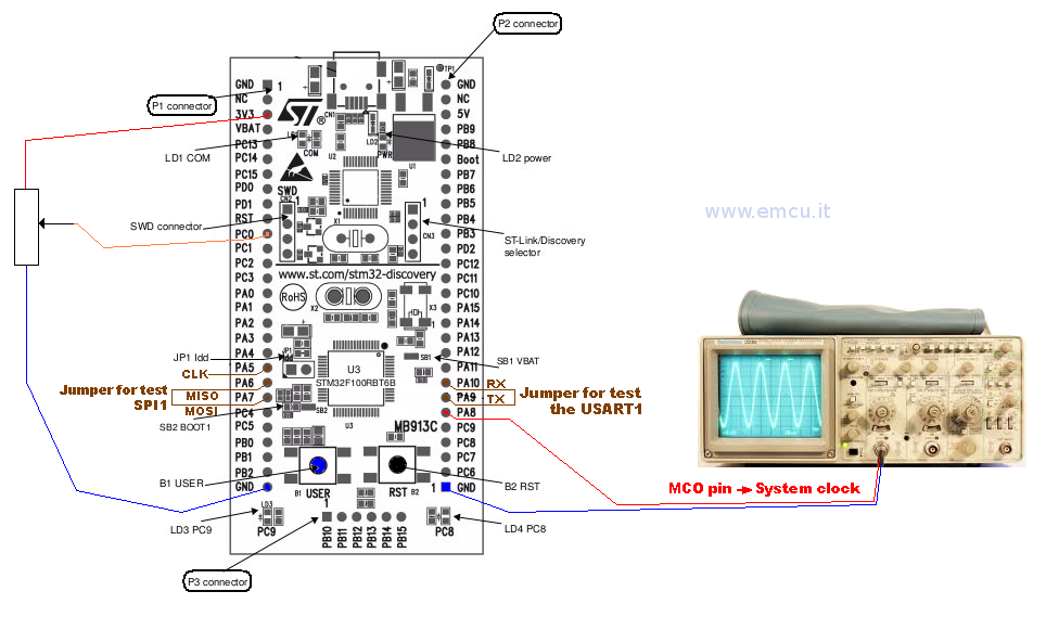
In this program we do the test of: I/O, ADC, DMA, USART1, SPI1 and MCO pin.
For do this is necessary only one trimmer (200K) and if you have an oscilloscope it is possible see the MCO output that is SYSCLK.
The image below show the configuration.
The practice is crucial to learn anything.
In this program we do the test of: I/O, ADC, DMA, USART1, SPI1 and MCO pin.
For do this is necessary only one trimmer (200K) and if you have an oscilloscope it is possible see the MCO output that is SYSCLK.
The image below show the configuration.
Explanations
There
are some things you should remember when you decide to use an STM32 and
the STM32-Library.
Please read also this: Two Words Concerning STM32 Library
Initialize the structure that refer the peripherals that you need to use
Configure correctly the I/O for use the peripherals
Clock the peripherals
Add the appropriate peripheral driver file into: StdPeriph-Driver
Configure the right SYSCLK that you need use in your application
Select the mcu that you need to use
Configure the file: stm3210x_conf.h
Configure the file: stm3210x.h
It's a must initialize the structure that refer the peripherals that you need to use, for do this are necessary two steps:
1) Declare the appropriate variable
/* Private variables ---------------------------------------------------------*/
GPIO_InitTypeDef GPIO_InitStructure;
RCC_ClocksTypeDef RCC_ClockFreq;
ErrorStatus HSEStartUpStatus;
ADC_InitTypeDef ADC_InitStructure;
DMA_InitTypeDef DMA_InitStructure;
USART_InitTypeDef USART_InitStructure;
SPI_InitTypeDef SPI_InitStructure;
/* Configure Leds (PC8 & PC9) mounted on STM32 Discovery board - OutPut Push Pull*/
GPIO_InitStructure.GPIO_Pin = GPIO_Pin_8 | GPIO_Pin_9;
GPIO_InitStructure.GPIO_Mode = GPIO_Mode_Out_PP;
GPIO_InitStructure.GPIO_Speed = GPIO_Speed_2MHz;
GPIO_Init(GPIOC, &GPIO_InitStructure);
// Configure SPI
SPI_InitStructure.SPI_Direction = SPI_Direction_2Lines_FullDuplex;
SPI_InitStructure.SPI_Mode = SPI_Mode_Master;
SPI_InitStructure.SPI_DataSize = SPI_DataSize_8b;
SPI_InitStructure.SPI_CPOL = SPI_CPOL_High;
SPI_InitStructure.SPI_CPHA = SPI_CPHA_2Edge;
SPI_InitStructure.SPI_NSS = SPI_NSS_Soft;
SPI_InitStructure.SPI_BaudRatePrescaler = SPI_BaudRatePrescaler_64;
SPI_InitStructure.SPI_FirstBit = SPI_FirstBit_MSB;
SPI_InitStructure.SPI_CRCPolynomial = 7;
SPI_Init(SPI1, &SPI_InitStructure);
SPI_Cmd(SPI1, ENABLE); /* Enable the SPI */
Make attention to configure correctly the I/O for use the peripherals.
Below there are the examples that show how to configure the I/O for use the:
Output, Input, ADC, USART1 and SPI1.
Don't forget to clock the peripherals.
All STM32 peripherals after the pawer-on are not clocked.
For clock the peripherals you must look where the peripherals are connected (APB1, APB2, AHB - see the block diagram of mcu).
Add the appropriate peripheral driver file into: StdPeriph_Driver (see below)
Don't forget to enable the external or internal oscillator that you need to use for SYSCLK.
At power-on for default is enabled the internal RC oscillator HSI.
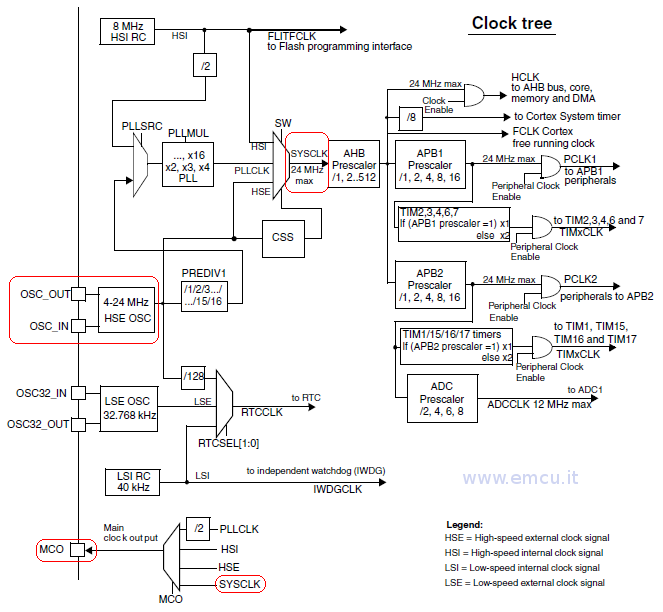
Remember tha there are different sources of clock that for stm32F100xx are:
● HSI oscillator clock (RC internal)
● HSE oscillator clock
● PLL clock
● 40 kHz low speed internal RC (LSI RC) which drives the independent watchdog and optionally the RTC used for Auto-wakeup from Stop/Standby mode.
● 32.768 kHz low speed external crystal (LSE crystal) which optionally drives the real-time clock (RTCCLK)
Normaly after the reset, the HSI oscillator (RC internal) as selected as system clock.
The HSI oscillator is 8MHz internal RC oscillator.
In our case we decide to use:
// Sets System clock frequency to 24MHz
SetSysClockTo24();
// Only for debug the clock tree ***********************************************
// Put the clock configuration into RCC_APB2PeriphClockCmd
RCC_APB2PeriphClockCmd(RCC_APB2Periph_GPIOA, ENABLE);
/* Output clock on MCO pin ---------------------------------------------*/
GPIO_InitStructure.GPIO_Pin = GPIO_Pin_8;
GPIO_InitStructure.GPIO_Mode = GPIO_Mode_AF_PP;
GPIO_InitStructure.GPIO_Speed = GPIO_Speed_50MHz;
GPIO_Init(GPIOA, &GPIO_InitStructure);
// RCC_MCOConfig(RCC_MCO_HSE); // Put on MCO pin the: freq. of external crystal
RCC_MCOConfig(RCC_MCO_SYSCLK); // Put on MCO pin the: System clock selected
//
// ******************************************************************************
/**
* Sets System clock frequency to 24MHz and configure HCLK, PCLK2 and PCLK1 prescalers.
*
* param None
* retval None
*/
void SetSysClockTo24(void)
{
/* SYSCLK, HCLK, PCLK2 and PCLK1 configuration -----------------------*/
/* RCC system reset(for debug purpose) */
RCC_DeInit();
/* Enable HSE */
RCC_HSEConfig(RCC_HSE_ON);
/* Wait till HSE is ready */
HSEStartUpStatus = RCC_WaitForHSEStartUp();
if (HSEStartUpStatus == SUCCESS)
{
/* Flash 0 wait state */
FLASH_SetLatency(FLASH_Latency_0);
/* HCLK = SYSCLK */
RCC_HCLKConfig(RCC_SYSCLK_Div1);
/* PCLK2 = HCLK */
RCC_PCLK2Config(RCC_HCLK_Div1);
/* PCLK1 = HCLK */
RCC_PCLK1Config(RCC_HCLK_Div1);
/* PLLCLK = (8MHz/2) * 6 = 24 MHz */
RCC_PREDIV1Config(RCC_PREDIV1_Source_HSE, RCC_PREDIV1_Div2);
RCC_PLLConfig(RCC_PLLSource_PREDIV1, RCC_PLLMul_6);
/* Enable PLL */
RCC_PLLCmd(ENABLE);
/* Wait till PLL is ready */
while (RCC_GetFlagStatus(RCC_FLAG_PLLRDY) == RESET)
{
}
/* Select PLL as system clock source */
RCC_SYSCLKConfig(RCC_SYSCLKSource_PLLCLK);
/* Wait till PLL is used as system clock source */
while (RCC_GetSYSCLKSource() != 0x08)
{
}
}
else
{
/* If HSE fails to start-up, the application will have wrong clock configuration.
User can add here some code to deal with this error */
/* Go to infinite loop */
while (1)
{
}
}
}
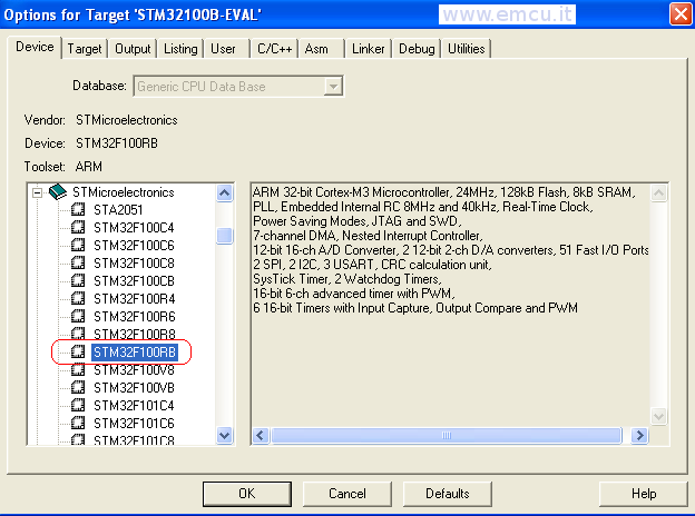
Select the mcu that you need to use.
For do this there are two steps to do.
First: select the eva-board that contain your mcu family, in our case is: STM32100B-EVAL
Configure the file: stm3210x_conf.h, see the line number from 25 to 49 and remove from the comment the peripheral that you need to use (see below).
Configure the file: stm3210x.h, see the line number from 49 to 58 and remove the comment from the line that identify the mcu that you need to use, in our case is: #define STM32F10X_MD_VL (see below).
Please read also this: Two Words Concerning STM32 Library
Initialize the structure that refer the peripherals that you need to use
Configure correctly the I/O for use the peripherals
Clock the peripherals
Add the appropriate peripheral driver file into: StdPeriph-Driver
Configure the right SYSCLK that you need use in your application
Select the mcu that you need to use
Configure the file: stm3210x_conf.h
Configure the file: stm3210x.h
It's a must initialize the structure that refer the peripherals that you need to use, for do this are necessary two steps:
1) Declare the appropriate variable
/* Private variables ---------------------------------------------------------*/
GPIO_InitTypeDef GPIO_InitStructure;
RCC_ClocksTypeDef RCC_ClockFreq;
ErrorStatus HSEStartUpStatus;
ADC_InitTypeDef ADC_InitStructure;
DMA_InitTypeDef DMA_InitStructure;
USART_InitTypeDef USART_InitStructure;
SPI_InitTypeDef SPI_InitStructure;
2)
Initialize the peripheral structure.
Below there is the I/O and SPI example.
/* Configure Leds (PC8 & PC9) mounted on STM32 Discovery board - OutPut Push Pull*/
GPIO_InitStructure.GPIO_Pin = GPIO_Pin_8 | GPIO_Pin_9;
GPIO_InitStructure.GPIO_Mode = GPIO_Mode_Out_PP;
GPIO_InitStructure.GPIO_Speed = GPIO_Speed_2MHz;
GPIO_Init(GPIOC, &GPIO_InitStructure);
// Configure SPI
SPI_InitStructure.SPI_Direction = SPI_Direction_2Lines_FullDuplex;
SPI_InitStructure.SPI_Mode = SPI_Mode_Master;
SPI_InitStructure.SPI_DataSize = SPI_DataSize_8b;
SPI_InitStructure.SPI_CPOL = SPI_CPOL_High;
SPI_InitStructure.SPI_CPHA = SPI_CPHA_2Edge;
SPI_InitStructure.SPI_NSS = SPI_NSS_Soft;
SPI_InitStructure.SPI_BaudRatePrescaler = SPI_BaudRatePrescaler_64;
SPI_InitStructure.SPI_FirstBit = SPI_FirstBit_MSB;
SPI_InitStructure.SPI_CRCPolynomial = 7;
SPI_Init(SPI1, &SPI_InitStructure);
SPI_Cmd(SPI1, ENABLE); /* Enable the SPI */
Make attention to configure correctly the I/O for use the peripherals.
Below there are the examples that show how to configure the I/O for use the:
Output, Input, ADC, USART1 and SPI1.
/* Configure Leds (PC8 & PC9) mounted on STM32 Discovery board - OutPut Push Pull*/
GPIO_InitStructure.GPIO_Pin = GPIO_Pin_8 | GPIO_Pin_9;
GPIO_InitStructure.GPIO_Mode = GPIO_Mode_Out_PP;
GPIO_InitStructure.GPIO_Speed = GPIO_Speed_2MHz;
GPIO_Init(GPIOC, &GPIO_InitStructure);
// Configure BLUE Botton (B1 User - PA0) on STM32 Discovery board - Input Floatting
GPIO_InitStructure.GPIO_Pin = GPIO_Pin_0;
GPIO_InitStructure.GPIO_Mode = GPIO_Mode_IN_FLOATING;
GPIO_Init(GPIOA, &GPIO_InitStructure);
// COnfigure ADC on ADC1_IN10 pin PC0
GPIO_InitStructure.GPIO_Pin = GPIO_Pin_0;
GPIO_InitStructure.GPIO_Mode = GPIO_Mode_AIN;
GPIO_Init(GPIOC, &GPIO_InitStructure);
/* Configure USART1 Tx (PA9) as alternate function push-pull */
GPIO_InitStructure.GPIO_Pin = GPIO_Pin_9;
GPIO_InitStructure.GPIO_Speed = GPIO_Speed_2MHz;
GPIO_InitStructure.GPIO_Mode = GPIO_Mode_AF_PP;
GPIO_Init(GPIOA, &GPIO_InitStructure);
/* Configure USART1 Rx (PA10) as input floating */
GPIO_InitStructure.GPIO_Pin = GPIO_Pin_10;
GPIO_InitStructure.GPIO_Mode = GPIO_Mode_IN_FLOATING;
GPIO_Init(GPIOA, &GPIO_InitStructure);
// Configure SPI - CLK PA5, MISO PA6, MOSI PA7
GPIO_InitStructure.GPIO_Pin = GPIO_Pin_5 | GPIO_Pin_6 | GPIO_Pin_7;
GPIO_InitStructure.GPIO_Speed = GPIO_Speed_2MHz;
GPIO_InitStructure.GPIO_Mode = GPIO_Mode_AF_PP;
GPIO_Init(GPIOA, &GPIO_InitStructure);
Click
here
to back to Explanations
Don't forget to clock the peripherals.
All STM32 peripherals after the pawer-on are not clocked.
For clock the peripherals you must look where the peripherals are connected (APB1, APB2, AHB - see the block diagram of mcu).
// Enable CLK
to port ADC1, GPIOC/A, USART1, SPI1
RCC_APB2PeriphClockCmd ( RCC_APB2Periph_ADC1 | RCC_APB2Periph_GPIOC |
RCC_APB2PeriphClockCmd ( RCC_APB2Periph_ADC1 | RCC_APB2Periph_GPIOC |
RCC_APB2Periph_GPIOA |
RCC_APB2Periph_USART1
| RCC_APB2Periph_SPI1, ENABLE);
/*
Enable DMA1 clock */
RCC_AHBPeriphClockCmd(RCC_AHBPeriph_DMA1, ENABLE);

RCC_AHBPeriphClockCmd(RCC_AHBPeriph_DMA1, ENABLE);
Click
here
to back to Explanations
Add the appropriate peripheral driver file into: StdPeriph_Driver (see below)
Click
here
to back to Explanations
Don't forget to enable the external or internal oscillator that you need to use for SYSCLK.
At power-on for default is enabled the internal RC oscillator HSI.
Remember tha there are different sources of clock that for stm32F100xx are:
● HSI oscillator clock (RC internal)
● HSE oscillator clock
● PLL clock
● 40 kHz low speed internal RC (LSI RC) which drives the independent watchdog and optionally the RTC used for Auto-wakeup from Stop/Standby mode.
● 32.768 kHz low speed external crystal (LSE crystal) which optionally drives the real-time clock (RTCCLK)
Normaly after the reset, the HSI oscillator (RC internal) as selected as system clock.
The HSI oscillator is 8MHz internal RC oscillator.
In our case we decide to use:
HSE
oscillator that is crystal oscillator (On the STM32 Discovery there is 8 MHz quartz mounted)
Configure the SYSCLK to 24MHz
Allow the SYSCLK to be output into the external MCO pin
Configure the SYSCLK to 24MHz
Allow the SYSCLK to be output into the external MCO pin
// Sets System clock frequency to 24MHz
SetSysClockTo24();
// Only for debug the clock tree ***********************************************
// Put the clock configuration into RCC_APB2PeriphClockCmd
RCC_APB2PeriphClockCmd(RCC_APB2Periph_GPIOA, ENABLE);
/* Output clock on MCO pin ---------------------------------------------*/
GPIO_InitStructure.GPIO_Pin = GPIO_Pin_8;
GPIO_InitStructure.GPIO_Mode = GPIO_Mode_AF_PP;
GPIO_InitStructure.GPIO_Speed = GPIO_Speed_50MHz;
GPIO_Init(GPIOA, &GPIO_InitStructure);
// RCC_MCOConfig(RCC_MCO_HSE); // Put on MCO pin the: freq. of external crystal
RCC_MCOConfig(RCC_MCO_SYSCLK); // Put on MCO pin the: System clock selected
//
// ******************************************************************************
/**
* Sets System clock frequency to 24MHz and configure HCLK, PCLK2 and PCLK1 prescalers.
*
* param None
* retval None
*/
void SetSysClockTo24(void)
{
/* SYSCLK, HCLK, PCLK2 and PCLK1 configuration -----------------------*/
/* RCC system reset(for debug purpose) */
RCC_DeInit();
/* Enable HSE */
RCC_HSEConfig(RCC_HSE_ON);
/* Wait till HSE is ready */
HSEStartUpStatus = RCC_WaitForHSEStartUp();
if (HSEStartUpStatus == SUCCESS)
{
/* Flash 0 wait state */
FLASH_SetLatency(FLASH_Latency_0);
/* HCLK = SYSCLK */
RCC_HCLKConfig(RCC_SYSCLK_Div1);
/* PCLK2 = HCLK */
RCC_PCLK2Config(RCC_HCLK_Div1);
/* PCLK1 = HCLK */
RCC_PCLK1Config(RCC_HCLK_Div1);
/* PLLCLK = (8MHz/2) * 6 = 24 MHz */
RCC_PREDIV1Config(RCC_PREDIV1_Source_HSE, RCC_PREDIV1_Div2);
RCC_PLLConfig(RCC_PLLSource_PREDIV1, RCC_PLLMul_6);
/* Enable PLL */
RCC_PLLCmd(ENABLE);
/* Wait till PLL is ready */
while (RCC_GetFlagStatus(RCC_FLAG_PLLRDY) == RESET)
{
}
/* Select PLL as system clock source */
RCC_SYSCLKConfig(RCC_SYSCLKSource_PLLCLK);
/* Wait till PLL is used as system clock source */
while (RCC_GetSYSCLKSource() != 0x08)
{
}
}
else
{
/* If HSE fails to start-up, the application will have wrong clock configuration.
User can add here some code to deal with this error */
/* Go to infinite loop */
while (1)
{
}
}
}
Click
here
to back to Explanations
Select the mcu that you need to use.
For do this there are two steps to do.
First: select the eva-board that contain your mcu family, in our case is: STM32100B-EVAL
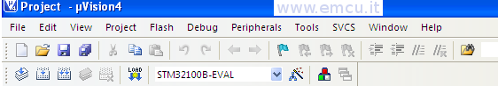
Second:
press on the icon:  and check the page below.
and check the page below.Click
here
to back to Explanations
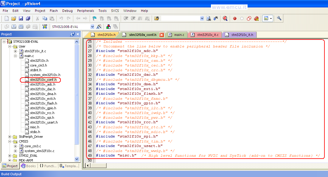
Configure the file: stm3210x_conf.h, see the line number from 25 to 49 and remove from the comment the peripheral that you need to use (see below).
/* Includes
------------------------------------------------------------------*/
/* Uncomment the line below to enable peripheral header file inclusion */
#include "stm32f10x_adc.h"
/* #include "stm32f10x_bkp.h" */
/* #include "stm32f10x_can.h" */
/* #include "stm32f10x_cec.h" */
/* #include "stm32f10x_crc.h" */
#include "stm32f10x_dac.h"
/* #include "stm32f10x_dbgmcu.h" */
#include "stm32f10x_dma.h"
#include "stm32f10x_exti.h"
#include "stm32f10x_flash.h"
// #include "stm32f10x_fsmc.h"
#include "stm32f10x_gpio.h"
/* #include "stm32f10x_i2c.h" */
/* #include "stm32f10x_iwdg.h" */
/* #include "stm32f10x_pwr.h" */
#include "stm32f10x_rcc.h"
/* #include "stm32f10x_rtc.h" */
/* #include "stm32f10x_sdio.h" */
#include "stm32f10x_spi.h"
/* #include "stm32f10x_tim.h" */
#include "stm32f10x_usart.h"
/* #include "stm32f10x_wwdg.h" */
#include "misc.h" /* High level functions for NVIC and SysTick (add-on to CMSIS functions) */
Click
here
to back to Explanations
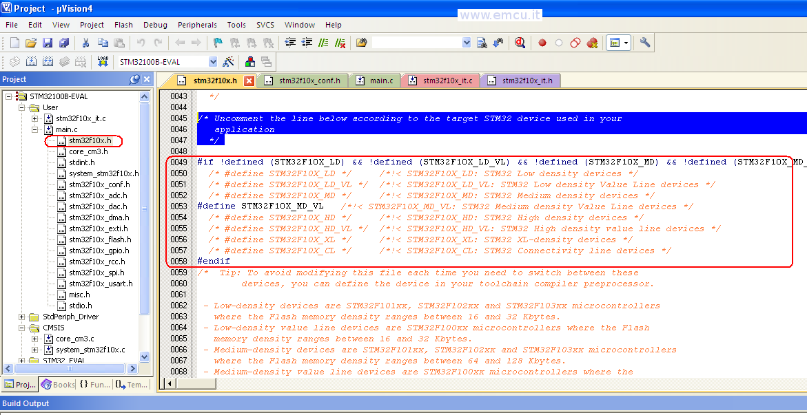
Configure the file: stm3210x.h, see the line number from 49 to 58 and remove the comment from the line that identify the mcu that you need to use, in our case is: #define STM32F10X_MD_VL (see below).
/* Uncomment the line below according
to the target STM32 device used in your application
*/
#if !defined (STM32F10X_LD) && !defined (STM32F10X_LD_VL) && !defined (STM32F10X_MD) && !defined (STM32F10X_MD_VL) && !defined (STM32F10X_HD) && !defined (STM32F10X_HD_VL) && !defined (STM32F10X_XL) && !defined (STM32F10X_CL)
/* #define STM32F10X_LD */ /*!< STM32F10X_LD: STM32 Low density devices */
/* #define STM32F10X_LD_VL */ /*!< STM32F10X_LD_VL: STM32 Low density Value Line devices */
/* #define STM32F10X_MD */ /*!< STM32F10X_MD: STM32 Medium density devices */
#define STM32F10X_MD_VL /*!< STM32F10X_MD_VL: STM32 Medium density Value Line devices */
/* #define STM32F10X_HD */ /*!< STM32F10X_HD: STM32 High density devices */
/* #define STM32F10X_HD_VL */ /*!< STM32F10X_HD_VL: STM32 High density value line devices */
/* #define STM32F10X_XL */ /*!< STM32F10X_XL: STM32 XL-density devices */
/* #define STM32F10X_CL */ /*!< STM32F10X_CL: STM32 Connectivity line devices */
#endif
/* Tip: To avoid modifying this file each time you need to switch between these
devices, you can define the device in your toolchain compiler preprocessor.
- Low-density devices are STM32F101xx, STM32F102xx and STM32F103xx microcontrollers where the Flash memory density ranges between 16 and 32 Kbytes.
- Low-density value line devices are STM32F100xx microcontrollers where the Flash memory density ranges between 16 and 32 Kbytes.
- Medium-density devices are STM32F101xx, STM32F102xx and STM32F103xx microcontrollers where the Flash memory density ranges between 64 and 128 Kbytes.
- Medium-density value line devices are STM32F100xx microcontrollers where the Flash memory density ranges between 64 and 128 Kbytes.
- High-density devices are STM32F101xx and STM32F103xx microcontrollers where the Flash memory density ranges between 256 and 512 Kbytes.
- High-density value line devices are STM32F100xx microcontrollers where the Flash memory density ranges between 256 and 512 Kbytes.
- XL-density devices are STM32F101xx and STM32F103xx microcontrollers where the Flash memory density ranges between 512 and 1024 Kbytes.
- Connectivity line devices are STM32F105xx and STM32F107xx microcontrollers.
*/
Click
here
to back to Explanations
In practice
Software
explanation:
Configure SYSCLK (System clock) to 24Mhz (HSE)
Send to the MCO (PA8) the SYSCLK
Configure LD3 & LD4 (Led)
LD4 flashes according with ADC measure
ADC (used on the ADC1_IN10 pin PC0) used in DMA mode that determines the speed of LD4 flashing
Push Button-BLUE (B1 USER) if is press the LD3 go ON
USART1 is configure to send the status of Push Button-BLUE (B1 USER - see the variable: RxChar)
The USART1
SetUp is:
SPI1 (used on PA5 (CLK), PA6
(MISO), PA7 (MOSI)
USART1 used in UART1 mode
BaudRate 9600
WordLength 8bit
StopBits 1
Parity NO
FlowControl None
BaudRate 9600
WordLength 8bit
StopBits 1
Parity NO
FlowControl None
SPI
is configure to send the status of Push Button-BLUE (B1 USER - see the
variable: SPI1val)
In this program we do the test of:
I/O
ADC via DMA
USART1
SPI1
MCO pin
How to use this program:
Using the KEIL IDE
We suppose that you use this program under debug.
When the program running you see the LD4 (blue) that flashing. The frequence depend of the value of the trimmer.
If you press B1 the LD3 go ON (green).
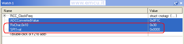
If you stop the code execution you must see the values below that means: B1 is PRESSED.

If you release B1 and stop the code execution you must see the values below that means: NO press on B1.
Using the ATOLLIC TrueSTUDIO Lite v2.1.0
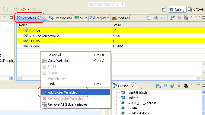
In debug for show the variables:
RxChar, SPI1val and ADCConvertedValue
you must enter in the Variables windows and then press the right mouse botton.
From the menu that appear select Add Global Variables.. and select the variables mentioned above.
See below.
We suppose that you use this program under debug.
When the program running you see the LD4 (blue) that flashing. The frequence depend of the value of the trimmer.
If you press B1 the LD3 go ON (green).
If you stop the code execution you must see the values below that means: B1 is PRESSED.

If you release B1 and stop the code execution you must see the values below that means: NO press on B1.
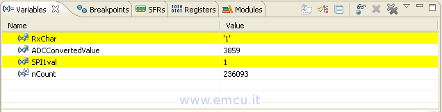
RxChar: monitor the UART1
SPI1val: monitor the SPI1
ADCConvertedValue: monitor the value of volt from the trimmer
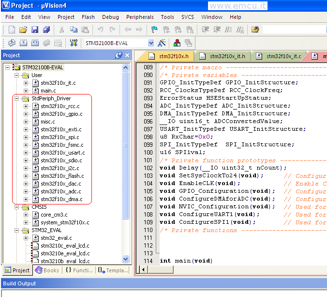
Software ready to use for KEIL
If you want receive this program ready to use for KEIL (STM32-Discovery-Test-forKEIL) please click here.
After you have unzipped the STM32-Discovery-Test you must go in the MDK-ARM directory and double click on Project.uvproj for run the KEIL IDE, see below.

Software ready to use for ATOLLIC
If you want receive this program ready to use for ATOLLIC TrueSTUDIO Lite v.2.1.9 (STM32-Discovery-Test-forAtollic) please click here.
After you have unzipped the STM32-Discovery-Test-forAtollic you must do:
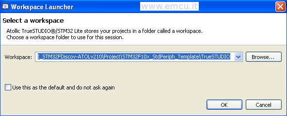
Run ATOLLIC TrueSTDUDIO Lite v.2.1.0 and select the TrueStudio directory.
In my case is:
C:\ESEMPI-SW\STM32-Examples\Lib340_IO-ADC-UART-SPI_STM32FDiscov-ATOLv210\Project\STM32F10x_StdPeriph_Template\TrueSTUDIO
see below.