
INDEX
Tools that are necessary
Introduction
Schematic of connections
The example explain how to...
Debounce
How to receive and run this example
Introduction
Schematic of connections
The example explain how to...
Debounce
How to receive and run this example
Tools that are necessary
Harware:
STM32 VL Discovery, see here
One trimmer of 200K
Some wires for connections
Optional is an oscilloscopre (Max freq > 25MHz)
Datasheet:
DS6517: Low & medium-density value line (STM32F100x4 STM32F100x6 STM32F100x8 STM32F100xB)
RM0041: STM32F100xx advanced ARM-based 32-bit MCUs
PM0056: STM32F10xxx/20xxx/21xxx/L1xxxx Cortex-M3 programming manual
PM0063: STM32F100xx value line Flash programming
PM0075: STM32F10xxx Flash memory microcontrollers
All of the datasheet for STM32F100RBT6 are here.
Software:
Windows XP (SP3)
STM Library version: V3.4.0
KEIL Version: uVision4
STM32 VL Discovery, see here
One trimmer of 200K
Some wires for connections
Optional is an oscilloscopre (Max freq > 25MHz)
Datasheet:
DS6517: Low & medium-density value line (STM32F100x4 STM32F100x6 STM32F100x8 STM32F100xB)
RM0041: STM32F100xx advanced ARM-based 32-bit MCUs
PM0056: STM32F10xxx/20xxx/21xxx/L1xxxx Cortex-M3 programming manual
PM0063: STM32F100xx value line Flash programming
PM0075: STM32F10xxx Flash memory microcontrollers
All of the datasheet for STM32F100RBT6 are here.
Windows XP (SP3)
STM Library version: V3.4.0
KEIL Version: uVision4
IDE-Version:
µVision V4.10
Toolchain: RealView MDK-ARM Version: 4.12
Toolchain Path: BIN40\
C Compiler: Armcc.Exe - V4.1.0.481 [Evaluation]
Assembler: Armasm.Exe - V4.1.0.481 [Evaluation]
Linker/Locator: ArmLink.Exe - V4.1.0.481 [Evaluation]
Librarian: ArmAr.Exe - V4.1.0.481 [Evaluation]
Hex Converter: FromElf.Exe - V4.1.0.481 [Evaluation]
CPU DLL: SARMCM3.DLL - V4.12
Dialog DLL: DARMSTM.DLL - V1.47
Target DLL: STLink\ST-LINKIII-KEIL.dll - V1.5.1
Dialog DLL: TARMSTM.DLL - V1.47
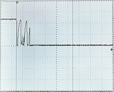
Introduction:
The mechanical properties of a
switch, when a switch is pressed, there is a period of time in which
the electrical connection "bounces" between open and closed.
It is important chose good Debounce Time for filtering the digital input noise.
Normaly the Deboundance Time must be from 5 to 30mS.
There are typically 2 methods employed to debounce a swtich:
It is important chose good Debounce Time for filtering the digital input noise.
Normaly the Deboundance Time must be from 5 to 30mS.
using
timer and interrupt to test the state of the switch
using polling method to test the state of the switch
In
this tutorial, we will be debouncing the swith using the SysTick (timer) and interrupt.
using polling method to test the state of the switch
Schematic of connections
The complete connections for test all the functionality is shown below

The example explains how to:
Configure SysTick to generate interrupt every 1mS
Implement a routine to read an Input (B1 User) with debounce
Implement a routine to read an Input (B1 User) with debounce
In this program we use also:
Configure SysClk to 24MHz and send it to MCO (PA8)
Configure Output to drive LEDs
Configure USART1 as UART
Configure SPI1
Configure ADC1 used in DMA
Explanation concenrning SysClk, OutPut, USART, SPI, ADC and DMA are here.
Configure Output to drive LEDs
Configure USART1 as UART
Configure SPI1
Configure ADC1 used in DMA
Explanation concenrning SysClk, OutPut, USART, SPI, ADC and DMA are here.
Debounce
There are typically 2 methods employed to debounce a swtich:
using
timer and interrupt to test the state of the switch
using polling method to test the state of the switch
using polling method to test the state of the switch
In
this tutorial, we will be debouncing the swith using the timer and interrupt.
What we want to do is reading and Input and implement a method for the debounce.
The idea is to use the SysClk configured to generate an interrupt every 1mS and use this interrupt for implementing the Input debounce.
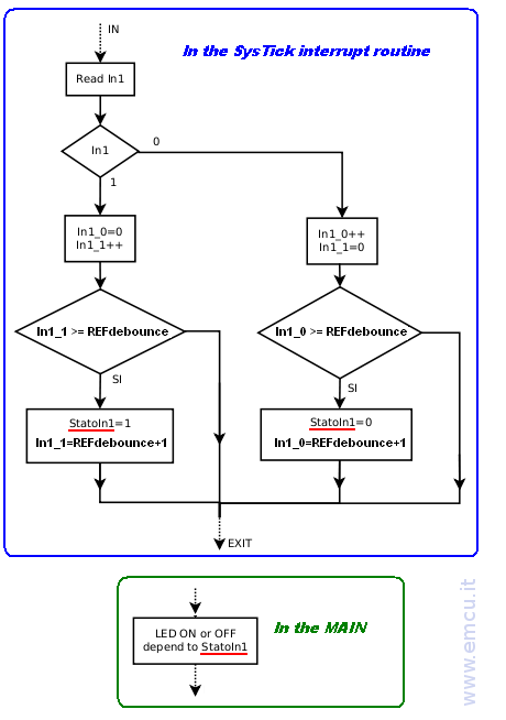
The flow diagram is below.
Note that using the flow below the Input is recognize at 1 or 0 if it stay at 1 or 0 for a time > of REFdebounce.
In another words, the 1 or the 0 must be 1 or 0 for all the REFdebounce Time.
If during the samples the imput change from 0 to 1 to 0 ecc, every change reset the In1_0 and In1_1.
In this way when In1_0 or In1_1 exceeds or is equal to REFdebounce means that it were at 1 or 0 for at least of the REFdebounce Time.
What we want to do is reading and Input and implement a method for the debounce.
The idea is to use the SysClk configured to generate an interrupt every 1mS and use this interrupt for implementing the Input debounce.
The flow diagram is below.
Note that using the flow below the Input is recognize at 1 or 0 if it stay at 1 or 0 for a time > of REFdebounce.
In another words, the 1 or the 0 must be 1 or 0 for all the REFdebounce Time.
If during the samples the imput change from 0 to 1 to 0 ecc, every change reset the In1_0 and In1_1.
In this way when In1_0 or In1_1 exceeds or is equal to REFdebounce means that it were at 1 or 0 for at least of the REFdebounce Time.
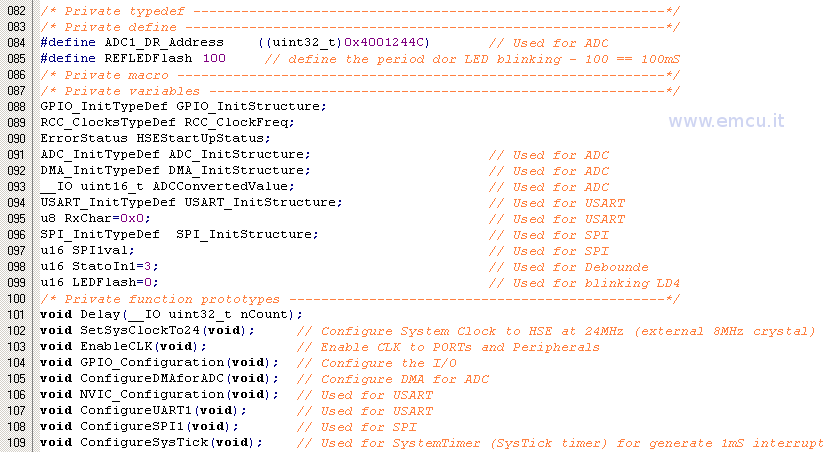
First we declared a global variables that are showed below.
This is in the: main.c
This is in the: stm32f10x_it.c

The variable named:
REFdebounce
indicates the time that is necessary for accept valid input.
REFdebounce is a multiple of 1mS.
REFdebounce
indicates the time that is necessary for accept valid input.
REFdebounce is a multiple of 1mS.
The second step is configure the SysTick, see below, line 209...217
This is in the: main.c

Inside the Interrupt of SysTick there is the reading of GPIOA PIN_0 (Read In1) and the first part of debounce (Debounce routine)
See below, lines 150...175
See below, lines 150...175

In the box below, lines 165...178, there is the implementation of the second part of debounce, this is in the main.c
Also there are:
Also there are:
LED blinking that depend of: REFLEDFlash + ADCConverterValue
USART send status of the button (B1 User)
SPI send status of the button (B1 User)
USART send status of the button (B1 User)
SPI send status of the button (B1 User)

For the software this is all.
Now, for testing this SW on STM32 Discovery, the connections are show below.
Now, for testing this SW on STM32 Discovery, the connections are show below.
We suppose that you use this program under debug.
When the program running you see the LD4 (blue) that flashing. The frequence depend of the value of the trimmer (ADCConverterValue) + REFLEDFlash.
If you press B1 the LD3 go ON (green) and the debounce depend of the value of: REFdebounce.
For example:
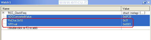
If you release B1 and stop the code execution you must see the values below that means: NO press on B1 .
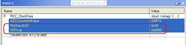
RxChar: monitor the UART1
SPI1val: monitor the SPI1
When the program running you see the LD4 (blue) that flashing. The frequence depend of the value of the trimmer (ADCConverterValue) + REFLEDFlash.
If you press B1 the LD3 go ON (green) and the debounce depend of the value of: REFdebounce.
For example:
set the REFdebounce at 5000, before see the LD3 ON or OFF you must press or release the B1 for 5 sec.
If you stop the code execution you must see the values below that means: B1 is PRESSED.If you release B1 and stop the code execution you must see the values below that means: NO press on B1 .
RxChar: monitor the UART1
SPI1val: monitor the SPI1
How to receive and run this example
If you
want receive this program (STM32-Discovery-Debounce) please click here.
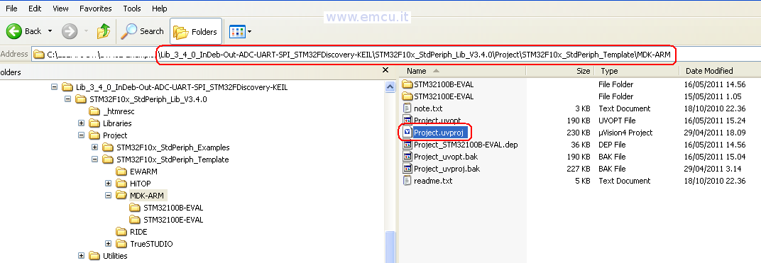
After you have unzipped the STM32-Discovery-Debounce you must go in the MDK-ARM directory and double click on Project.uvproj for run the KEIL IDE, see below.
After you have unzipped the STM32-Discovery-Debounce you must go in the MDK-ARM directory and double click on Project.uvproj for run the KEIL IDE, see below.
LINK: