
STM32F0xx Page
Basic Functions
Suggested improvement
Electronic scheme
Software & Doc
-
Introduction
This project is intended to release you the basic info for realize an electronic board for control an automatic gate.
Using this project you can control two different automatic gates that are:
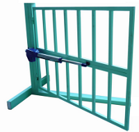
Single Swing Gate
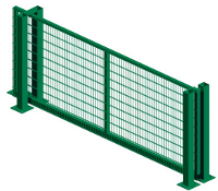
Single Sliding Gate
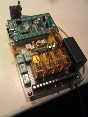
This project is based on the STM32F0-Discovery.
Here you find the basic software for testing the electronic board, the schematic and the pins allocation.
You must write the software for control your automatic gate.
As it is a custom project, are present the uncommon functions listed below:
- Crepuscular light sensor that turns on the outside lights at night. When the gate is closed the lights is turn off after a time that depend of the value of the Temp.RLuci (RegularConvData_Tab[0]).
- Blinking LAMP at 220Vac (it indicates that the gate is in motion).
- Input for PHOTOCELL but if for your application is a mandatory, you simply connect an external Photocell to PE input that stop the gate.
- Input for Remote Control but if for your application is a mandatory, you simply connect an external Remote Control to PP input.
Also, using relays, I have saved a lot of solder joints, but of course is not cheaper if you must buy the new relays.
I suggest the schematic below for substitute the relays in input.

You should choose R5, R1 and R2 to have the right input voltage supported by your MCU input pins.
The formulas to calculate the resistors are shown below.
Vi
| R1 R2
| ____ ____
|---|____|---------|____|----- GND
|<--- Vr1 --->|<--- Vr2 --->|
|
Vr2 = ( Vi / (R1+R2 ) )* R2
Vr1 = ( Vi / (R1+R2 ) )* R1
Suppose that MCU is powered at 3V and that Vi is 12V the resistor must be:
R5 == 9,7K
R1 == 330
R2 == 3,3K
Vr2 == 2,970V
Basic Functions
StatoLampeggioLedVerde
= SPENTO;
The
blinking Green LED is OFF
StatoLampeggioLedVerde
= ACCESO;
The
blinking Green LED is ON
VLed_OFF;
The
Green LED is turned OFF
StatoLampeggioLedBlu
= SPENTO;
The
blinking Blue LED is OFF
StatoLampeggioLedBlu
= ACCESO;
The
blinking Blue LED is ON
BLed_OFF;
The
Blue LED is turned OFF
statoLampeggiante
= SPENTO;
The
blinking LAMP is OFF
statoLampeggiante
= ACCESO;
The
blinking LAMP is ON
LAMP_OFF;
The
LAMP is turned OFF
AttesaPressioneTastoBLU();
Waiting
until the Blue Button is pressed and released.
The
Blue Button is on the STM32F0-Discovery.
Delay(n);
Set
a delay of n ms. If n==1000 the delay is 1sec
The ADC input channels are used under DMA and the allocation is show below.
|
Name |
Simbol |
PIN |
Function |
Name of channel |
Tab position |
|
Tempo Luce di Cortesia |
TLC |
PA1 |
Analog |
ADC_Channel_1 |
RegularConvData_Tab[0] |
|
Crepuscolare |
CRE |
PA7 |
Analog |
ADC_Channel_7 |
RegularConvData_Tab[1] |
|
Reserved |
PWM |
PA3 |
Analog |
ADC_Channel_3 |
RegularConvData_Tab[2] |
|
Sensibilità Crepuscolare |
SC |
PA2 |
Analog |
ADC_Channel_2 |
RegularConvData_Tab[3] |
You
see an easy example how to use the:
Tempo
Luce di Cortesia → RegularConvData_Tab[0]
Sensibilità
Crepuscolare → RegularConvData_Tab[3]
in
main.c by finding the
“ COMMENT ”
flag.
You
see how to use the:
Crepuscolare
→ RegularConvData_Tab[1]
in main.c by finding the “ Test
Crepuscular Light Sensor
” flag.
Suggested improvement
Add a motor speed control also called: gate’s final opening/closing phase slow-down speeds.
-
Electronic scheme
The electronic scheme is below, for see large image click on it.
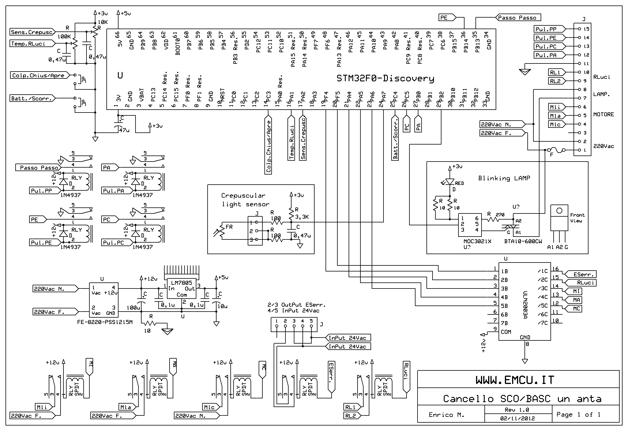
Remember to dissipate the LM7805.
The FR (PHOTORESISTOR) is 2..20K, 100mW and it is find here (cod.2510-LDR04) and here (LDR04).
The FE-8220-PSS1215M also called PSS1215M and it is find here (cod.8220-PSS1215M) and here.
Below there are some photo of my board.

-
Software and Doc
For download the Software and Doc click here and download: STM32F0-AutomaticGate
This SW was tested on KEIL ver.4.60 - 32K free version.
that is in the folder:
C:\......\F0_CANC_TEST_LibV1.0.0\Project\STM32F0xx_StdPeriph_Templates\MDK-ARM
Inside the directory tree there are the folders below.
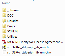
In the DOC folder there are the components data sheet and in the .ods and .xls file there are the pins allocation and the explanation of the test sequence.
In the SCHEMI folder there is the electronic scheme in .bmp format.