
RaspBerry Pi

English version coming soon...

- Low price
- Expansion connector for interface RaspBerry Pi to external world (GPIO, SPI, I2C and UART).
- All the standard peripherals are present (Ethernet, USB, SD card, TFT, etc).
- The only negative is that the documentation is abundant, but is scattered on different websites. This cause a difficulty to find the right information.
For try to concentrate the mainly information on one website I did this manual.
Operating system
Make a SD card
Turn-Off the RaspBerry Pi
LEDs on RaspBerry Pi
Raspi Configurator
Default User
ifconfig
Discovery the IP of our RaspBerry Pi from remote PC
nmap, to find out the IP address of your Raspberry Pi using a PC with LINUX
Angry IP Scanner, to find out the IP address of your Raspberry Pi using a PC with WINDOWS
Control RaspBerry Pi from remote PC
How to use a remote terminal using Putty o Kitty (PC with WINDOWS)
How to use a remote terminal (PC with LINUX)
The graphics from remote
For PC with LINUX
For PC with Windows
Manage remote files from your PC with LINUX to the RaspBerry Pi
Manage remote files from PC with WINDOWS to the RaspBerry Pi Windows
How to connect a USB WiFi (SITECOM N300)
Control the status of the WiFi connection
cron scheduler example
RaspBerry Pi as a Wireless Hotspot
Control the RaspBerry Pi from Android
How to install a server Apache2, PHP5 and the relative libraries
How to install the data base MySQL, plus the package for PHP5, etc
Graphics interface for MySQL
How to manage a new Data Base
PYTHON
Version of Python
Development Environments (IDE)
Library for manage the GPIO
Layout of the I/O GPIO connector
General purpose libraries
GPIO in OutPut mode
Flashing the GPIO4
GPIO in InPut mode
How to reading the GPIO27 (InPut)
How to measure a Temperature using an NTC and the expansion board FT1060M
NTC thermistors and the relevant formulas for their linearization
How to manage the Concurrency
How to configure the I2C bus
How to configure the RS232 / UART
SPI
Expansion board FT1060M
Mapping of ADC, DAC, etc
How many RaspBerry Pi are available today ?
LINUX basic commands
NTC Thermistors and relevant formulas for their linearization
My SW examples
How to run a LINUX process in background
Summary of basic commands to connect to the Raspberry Pi from a remote PC with installed LINUX
Link
If you read here means that you are holding a Raspberry Pi board and maybe you are eager to use it, but if you didn't documented yourself before, now you must buy also:
- SD Card da 4/8Gbyte
I recommend you choose a fast SD because the performance of your Raspberry Pi will be affected by the speed of the SD you choose. - USB keyboard
- USB mouse
- RJ45 cable for connect your RaspBerry Pi to the Modem ADSL e/o Router
- Monitor or TV with HDMI interface
- 5V USB power supply - 1A to 1,5A (remember that we will use also expansion board and USB WiFi)
- USB cable - USB-A to Micro-USB
- Optionally an USB-WiFi adapter
Now you must connect the peripherals shown below in red.

The Raspberry Pi is designed to work with Linux but we
know that there are different versions, on this manual we uase the Raspbian
"wheezy" (derived from Debian).
Raspbian is the recommended Linux version for RaspBerry Pi.
Download and install the Raspbian on
SD
card.
On Internet there are a lot of explanation, I highlight below some
links.
For who use a PC
with Windows see below:
http://www.raspberrypi.org/wp-content/uploads/2012/12/Raspberry_Pi_-_Guida_veloce.pdf
(In Italian language)
http://www.raspberrypi.org/wp-content/uploads/2012/04/quick-start-guide-v2_1.pdf
(In English language)
For who use a LINUX
or MAC see below:
http://www.raspberrypi.org/downloads
Here is my step by step for download and install Raspbian on SD card of 8GB.
-
Format your SD card as FAT32
For who use LINUX I suggest to use gparted.
For who use Windows I suggest to use Win32DiskImager. -
Download RaspBian from here:
http://www.raspberrypi.org/downloads
in the Internet page go down untill you find the RaspBian image (see below).

- After the download, unzip the file and you get a file with extension .img
- For install this file on the SD card from Linux I suggest to use the ImageWriter, if on your Linux distribution is not istalled use your Software Center for install it.

NOTE:
For Turn Off your
RaspBerry Pi use the command:
sudo shutdown -h now
or
sudo halt
ATTENTION:
This problem does not exist if you use your Raspberry Pi remotely connected so you do not have anything except the RJ45 cable to your LAN (Ethernet).
LEDs on RaspBerry Pi
On the RaspBerry Pi there are 5 leds that are:
Color
Name
ORANGE 100
GREEN LINK
GREEN
FDX
RED PWR
GREEN ACT
During normal run
the led 100, LINK, FDX and PWR are ON, and sometime flashing the led
ACT (ACT when is on, highlight the access to the SD card).
When the RaspBerry Pi is stopped, only the PWR is ON, remember that for
turn off is necessary do the command below.
sudo shutdown -h now
When is ON only the led PWR (all other leds are OFF), is possible remove the power to RaspBerry Pi.
If you use only the USB WiFi for connect the RaspBerry Pi to the Access Point, you see ON only the led PWR and sometime flashing the led ACT (ACT when is on, highlight the access to the SD card).

Raspi Config
This is a configuration utility tha is run
automaticaly at first power on of your RaspBerry Pi.
This utility permit to configure your RaspBerry Pi.
For execute the configuration utility using this
command (from terminal/shell):
sudo raspi-config
For surfing inside the menù use the arrow keys and the tab key.
The fundamental things that you must do are:
-
configure the keyboard
-
do the update of the SW
-
espand the filesystem, this is for use all the space that there are on SD card.
-
Configure your local time, during this configuration you must chose a server where your RaspBerry Pi find the references for your local time.
Remember that on the RaspBerry Pi is not present a RTC, the only way to mantain your RaspBerry time after a power on is a Internet connection.
-
Enable the ssh, is wery important because by this way we have the possibility to control from a remote PC our RaspBerry Pi.
For do this chose:
Advanced Options
SSH -
If you enable boot_behavior after the power on is started the graphics interface of Raspbian (LXDE).
I suggest to not enable this option, in any case is possible start the LXDE using the command:
startx
from a terminal.
raspberry login:
pi
password:
raspberry
I suggest you to change the password from the menù: change_pass
At this point your RaspBerry Pi is configured and running.
Our key point is to use the RaspBerry Pi without display, keyboard and mouse, for this reason is important to know the IP address of our RaspBerry Pi (related to the lan where RPi is connected, normaly our network at home).
For discovery the IP address of your RaspBerry Pi there are different possibility, one is to use the command ifconfig from a terminal of our RaspBerry Pi:
ifconfig
indirizzo inet:192.168.1.9 Bcast:192.168.1.255 Maschera:255.255.255.0
indirizzo inet6: fe80::21d:9ff:fea5:9348/64 Scope:Link
UP BROADCAST RUNNING MULTICAST MTU:1500 Metric:1
RX packets:2939234 errors:0 dropped:9 overruns:0 frame:0
TX packets:1501509 errors:0 dropped:0 overruns:0 carrier:0
collisioni:0 txqueuelen:1000
Byte RX:2289590583 (2.2 GB) Byte TX:466379381 (466.3 MB)
Interrupt:17
lo
Link encap:Loopback locale
indirizzo
inet:127.0.0.1 Maschera:255.0.0.0
indirizzo inet6:
::1/128 Scope:Host
UP LOOPBACK
RUNNING MTU:16436 Metric:1
RX packets:47074
errors:0 dropped:0 overruns:0 frame:0
TX packets:47074
errors:0 dropped:0 overruns:0 carrier:0
collisioni:0
txqueuelen:0
Another way to find the IP is:
nmap
Discovery the IP of our RaspBerry Pi from remote PC
Suppose that your RaspBerry Pi is connected to a LAN,
for discovery the IP address of it, follow the explanations below.
From a remote PC with LINUX (connected to the same LAN) open a terminal and use the command:
nmap -sP 192.168.1.1-255
obviously change the: 192.168.1.1
and use the IP address for your Access Point or Router.
You receive an answer from the nmap command, similar to the image below.
Nmap scan report for vodafone.station (192.168.1.1)
Host is up (0.00094s latency).
Nmap scan report for fritz.repeater.station (192.168.1.4)
Host is up (0.015s latency).
Nmap scan report for rpi1.station (192.168.1.5)
Host is up (0.0014s latency).
Nmap scan report for enricohp.station (192.168.1.7)
Host is up (0.0026s latency).
Nmap scan report for enrico-MM061.station (192.168.1.9)
Host is up (0.00028s latency).
Nmap scan report for DCS-930L-DestroCortile.station (192.168.1.10)
Host is up (0.0017s latency).
Nmap scan report for DCS-930L-Pedonale.station (192.168.1.11)
Host is up (0.0016s latency).
Nmap scan report for DCS-930L-SinistroCortile.station (192.168.1.12)
Host is up (0.0023s latency).
Nmap done: 255 IP addresses (8 hosts up) scanned in 3.33 seconds
My RaspBerry Pi name is: rpi1.station and the IP is: 192.168.1.5
ATTENTION: if nmap is not present on your Linux distribution, install it using the following command:
sudo apt-get install nmap
or
sudo su
install nmap
If you use a remote PC with Windows, for discovery the IP address of your RaspBerry Pi, I suggest to use: Angry IP Scanner that is free.
Below a immage of a scan of a LAN.

Control RaspBerry Pi from remote PC
Normally,
the Raspberry Pi is used in control applications, and is mounted in
cabinets or in places difficult to access, which is why it is essential
to remote the control of our Raspberry Pi by using a remote PC.
To do what is written above, there are several possibilities that are:
-
Remote control by Ethernet
-
Remote control by RS232
Leaving aside the possibility of using the RS232 due to the fact that on modern PCs no longer exists, we will focus on remote control via Ethernet.
To control via the Internet Raspberry Pi is essential to have enabled in the configuration, the SSH server. If you have not already done so read here.
In practice, the control is carried out as shown in the figure below.

How to use a remote terminal using Putty o Kitty (PC with WINDOWS)
The first thing to do is to install: PUTTY
o KITTY
(install it on PC with LINUX but also on PC with Windows)
By using Putty or Kitty we have the possibility to control our
RaspBerry Pi using remote PC and a terminal (shell).
We will use PUTTY which is the best remote terminal written for the Linux world and also available for Windows.
Also in this case there are several guides on how to configure PUTTY (found it on the Internet) and below I've marked someones, see link.
The key things to do are:
-
Enter the IP address of the Raspberry Pi, on how to locate the IP address see here.
-
Save the configuration.
For your convenience I have put below the main windows PUTTY you will need to fill out; see the red rectangles.

ATTENTION:
To find out how to locate the IP address of your Raspberry Pi read here

ATTENTION:
LINK
-
http://www.engeene.it/controllare-da-remoto-una-raspberry-pi/
-
http://raspberrypi4dummies.wordpress.com/2013/03/17/connect-to-the-raspberry-pi-via-ssh-putty/
-
http://cplus.about.com/od/raspberrypi/a/How-Do-I-Setup-Ssh-On-Raspberry-Pi.htm
How to use a
remote terminal (PC with LINUX)
You must know the IP address of your IP del RaspBerry
Pi, (see here
or use the command nmap see here.
To log on to your Raspberry Pi, you
have two possibilities: via terminal using the command ssh or use PUTTY.
-
SSH
From a remote PC use the command:
ssh IndirizzoIPdelRaspBerry -l pi
remember that pi is default login or RaspBerry Pi, if you have changed it you must change also here.
EXAMPE:
ssh 192.167.111.31 -l pi
obviously 192.167.11.31 is the IP of my RaspBerry Pi, change this IP with your IP
ATTENTION:
On my PC where I have Xubuntu, occasionally, by using the ssh command I happen to not be able to login to the restart of the PC, see here.
-
PUTTY
This is the mode that I recommend because PUTTY is available for both LINUX and Windows and works perfectly.
To install it, go to the Software Center and download it to your PC.
The graphics from remote
On our Raspberry Pi there is Linux version: Raspbian,
it is also available a graphical interface which is called X.
Directly from a shell of RaspBian we can launch the GUI by running the
command:
startx
If we want to use graphics from remote PC we should have installed an X emulator.
See below.
Graphics for remote PC with LINUX
By using a remote PC and Linux you have different possibility, here we show two possibility, see below.
1)
VNC server
On RaspBerry Pi
Install the VNC server on your RaspBerry Pi, for do this, after you have connected your remote PC to your RaspBerry, use the command:
sudo apt-get install tightvncserver tightvnc-java
Now start the server:
vncserver
:1 -geometry 1200x700 -depth 24
During the installation the
vncserver ask you to insert a password,
chose one easy to remember.
Obviously replaced 1200x700 with resolution of your remote PC.
To start
the vncserver automatically at power on of your Raspberry Pi do
this:
- sudo bash
- nano /etc/rc.local
We will open the nano editor on the file rc.local, at this point included in the file the command shown in the red box, see below:
 Of
course you must replace 1200x700 with a resolution to use on your
remote PC and if you have changed the user name (pi) change it also
here.
Of
course you must replace 1200x700 with a resolution to use on your
remote PC and if you have changed the user name (pi) change it also
here.
- chmod 777 /etc/rc.local
- exit
If you now switch off and switch on your Raspberry Pi will be automatically reload the vncserver.
NOTE:
- Give a lower resolution than that of your remote PC so as to have a window in which there are not the vertical and horizontal scrollbars.
- After a power on if your
RaspBerry Pi do not accept by remote PC a connection by vncviewer do
this:
From a remote PC connected in terminal mode to your RaspBerry Pi do the command:
vncserver :1 -geometry 1200x700 -depth 24
On remote PC (that use Linux)
On your remote PC now is necessary install vncviewer, for do this open a terminal and follow the instructions below.
sudo
apt-get install vncviewer
For run vncviewer use the command:
vncviewer 192.168.1.3:1
Obviously, replace 192.168.1.3 with the IP address of your Raspberry Pi, see here.
2) ssh
ssh -X 192.167.111.31
Obviously, replace 192.168.1.3 with the IP address of your Raspberry Pi, see here.
Now if you write the name of a program that uses graphics this will run and you can also control it from your remote PC.
For example, to launch the RaspBian X interface, type: startx
Graphics for remote PC with WINDOWS
If on your remote PC you use Windows I suggest you to use this X emulator that is free.
Another possibility
is to use Xming
that is X server and is open source.
Manage remote files from your PC with LINUX to the RaspBerry Pi
From a terminal/shell from the remote PC you can use
the commands below.
Please read this note.
Copying files from: PC to Raspberry Pi
scp LocalFile RemotePCName@IPaddress:DestinationFile
example:
scp geo.pdf pi@192.168.1.3:~/geo.pdf
Copying
file from: RaspBerry Pi to PC
scp pi@192.168.1.3:~/PY/P1.py P1.py
We taken the file P1.py from the directory of the Raspberry Pi: /home/pi/PY
and copied it on your PC in the directory where you are.
Copying directory from: remote PC to RaspBerry Pi
On RaspBerry Pi is necessary create the destination directory, for example:
cd /var/www
do the new directory:
sudo mkdir phpMyAdmin-4.1.2-all-languages
enable all privileges:
sudo chmod 777 phpMyAdmin-4.1.2-all-languages
at this point from the remote PC use the command below:
scp -rpC phpMyAdmin-4.1.2-all-languages pi@192.168.1.3:/var/www/
pi@192.168.1.3 - change this with your address of RaspBerry Pi
phpMyAdmin-4.1.2-all-languages
this is the directory that is on remote PC and that we want to copy on
the RaspBerry Pi.
/var/www/
is the directory on the RaspBerry Pi
where we copy the files.
Manage remote files from PC with WINDOWS to the RaspBerry Pi Windows
For who use on remote PC Windows I suggest to use the WinSCP see the link below.
http://winscp.net/eng/download.php
How to connect a USB WiFi (SITECOM N300)
Log on to our Raspberry Pi using the RJ45 cable
is definitely very reliable but also inconvenient, it is certainly more
convenient to use a connection via WiFi key.
To do this you can use a lot of WiFi keys, here is a list of the keys
compatible with our Raspberry Pi.
I, wanting to have a significant distance between my AP and my Raspberry Pi, I chose a WiFi dongle with an external antenna and the choice fell on SITECOM N300.
This usb WiFi is among those that are recognized by RaspBian immediately, no need to install drivers or SW, the only thing you need to do is configure it by following the steps below.
sudo nano /etc/network/interfaces
insert in the file the line in red below.
iface lo inet loopback
iface eth0 inet dhcp
allow-hotplug wlan0
iface wlan0 inet dhcp
wpa-conf /etc/wpa_supplicant/wpa_supplicant.conf
iface default inet dhcp
Save the file (ctrl+X)
sudo nano /etc/wpa_supplicant/wpa_supplicant.conf
insert in the file the line in red below.
Change the line in bold red in according to the configuration of your A.P.
update_config=1
network={
ssid="A.P. name"
psk="Password of your A.P."
proto=WPA
key_mgmt=WPA-PSK
pairwise=TKIP
auth_alg=OPEN
}
Save the file (ctrl+X)
Turn off and turn on your RaspBerry Pi and that is all, now you have the WiFi connection.
On my A.P. (Vodafone Station 2) the RaspBerry Pi need around 2min to establish the WiFi connection.
If on your remote PC use the command: nmap
and your RaspBerri Pi is connected to Ethernet via RJ45 and via USB WiFi you must see something like below.
enrico@enrico-MM061:~$
nmap
-sP 192.168.1.1-255

Starting
Nmap 5.21 ( http://nmap.org ) at 2013-12-28 01:00 CET

Nmap
scan report for vodafone.station (192.168.1.1)

Host
is up (0.0011s latency).

Nmap
scan report for android-9e52b9407176d692.station (192.168.1.2)

Host
is up (0.051s latency).

Nmap
scan report for android-b1a38c6c82d7340e.station (192.168.1.3)

Host
is up (0.032s latency).

Nmap
scan report for fritz.repeater.station (192.168.1.4)

Host
is up (0.062s latency).

Nmap
scan report for enrico-MM061.station (192.168.1.6)

Host
is up (0.00038s latency).

Nmap
scan report for enricohp.station (192.168.1.7)

Host
is up (0.034s latency).

Nmap
scan report for rpi1.station (192.168.1.9)

Host
is up (0.0099s latency).

Nmap
scan report for DCS-930L-DestroCortile.station (192.168.1.10)

Host
is up (0.00080s latency).

Nmap
scan report for DCS-930L-Pedonale.station (192.168.1.11)

Host
is up (0.00075s latency).

Nmap
scan report for DCS-930L-SinistroCortile.station (192.168.1.12)

Host
is up (0.00075s latency).

Nmap
scan report for rpi1.station (192.168.1.14)

Host
is up (0.034s latency).

Nmap
done: 255 IP addresses (11 hosts up) scanned in 3.40 seconds

enrico@enrico-MM061:~$
If now you retype the command nmap you must see something like below.
enrico@enrico-MM061:~$
nmap
-sP 192.168.1.1-255

Starting
Nmap 5.21 ( http://nmap.org ) at 2013-12-28 01:22 CET

Nmap
scan report for vodafone.station (192.168.1.1)

Host
is up (0.0018s latency).

Nmap
scan report for android-b1a38c6c82d7340e.station (192.168.1.3)

Host
is up (0.012s latency).

Nmap
scan report for fritz.repeater.station (192.168.1.4)

Host
is up (0.0057s latency).

Nmap
scan report for enrico-MM061.station (192.168.1.6)

Host
is up (0.00028s latency).

Nmap
scan report for enricohp.station (192.168.1.7)

Host
is up (0.0030s latency).

Nmap
scan report for DCS-930L-DestroCortile.station (192.168.1.10)

Host
is up (0.0012s latency).

Nmap
scan report for DCS-930L-Pedonale.station (192.168.1.11)

Host
is up (0.0011s latency).

Nmap
scan report for DCS-930L-SinistroCortile.station (192.168.1.12)

Host
is up (0.0012s latency).

Nmap
scan report for rpi1.station (192.168.1.14)

Host
is up (0.0057s latency).

Nmap
done: 255 IP addresses (9 hosts up) scanned in 3.44 seconds

enrico@enrico-MM061:~$
The WiFi address is: 192.168.1.14
For more info see: Debian Network setup
Control the status of the WiFi connection
It is possible that sometime go off your router or access point where is connect your WiFi in use on the RaspBerry Pi.
For restart the WiFi connection I made this shell script (WiFiTest.sh).
echo " "
echo "Test the WiFi connection"
if ifconfig wlan0 | grep -q "inet addr:" ; then
echo "*** The WiFi connection is OK ***"
else
echo " Problems with WiFi - Force down the: wlan0"
ifdown --force wlan0
sleep 1
echo " Restart the: wlan0"
ifup wlan0
sleep 1
fi
echo " "
echo "Please wait 5sec, a second test of WiFi is being processed"
sleep 5
if ifconfig wlan0 | grep -q "inet addr:" ; then
echo "*** The WiFi connection is OK ***"
else
echo " Problems with WiFi - Force down the: wlan0"
ifdown --force wlan0
sleep 1
echo " Restart the: wlan0"
ifup wlan0
sleep 1
fi
echo "END Test of the WiFi connection"
echo " "
exit
Remember that for run the above shell you must use this syntax:
- Give to file and the users, all the permission.
- chmod 777 WiFiTest.sh
- The command below is for run the WiFiTest.sh, I suppose that you are in the directory where is the WiFiTest.sh
- sudo ./WiFiTest.sh
For schedule the execution of my WiFiTest.sh I use cron.
add to the end of file the line below:
*/1 * * * * sudo /home/pi/Utility/WiFi/WiFiTest.sh >/tmp/tmp.txt
Save the file using CTRL+X and next Y(es).
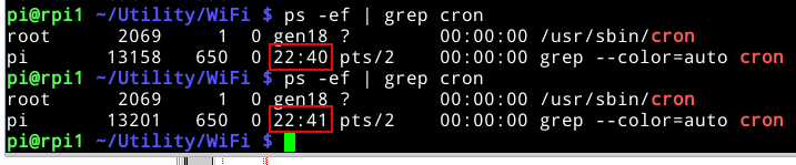
For checking if really every minute cron is executed, use two command below at the distance of one minute.
ps -ef | grep cron
See the two reds box below.
To see the result of the operation see the file /tmp/tmp.txt (see below, use the command: cat /tmp/tmp.txt).
*** The WiFi connection is OK ***
Please wait 5sec, a second test of WiFi is being processed
*** The WiFi connection is OK ***
END Test of the WiFi connection
Control the mcu temperature on your RaspBerry Pi from remote terminal
To know the temperature of cpu use the command below from terminal/shell.
vcgencmd measure_temp

Control the RaspBerry Pi from Android
With phones using android as operating system you can remotely control your Raspberry Pi.
If you go here:
https://play.google.com/store/apps
and try to type: Raspberry Pi
you will see many apps available for the most varied fields of use.
Some
applications, the most advanced, those that directly control the GPIO,
require the installation of a dedicated software on the Raspberry Pi,
but if you just want to know if your Raspberry Pi is working then I
suggest: RasPi Check
https://play.google.com/store/apps/details?id=de.eidottermihi.rpicheck
Below you can see some of the parameters that will be displayed.
This application allows you to make even turning off the Raspberry Pi.

How to install a server Apache2, PHP5 and the relative libraries
For install Apache2 use the command below:
sudo apt-get install apache2
For install PHP5 use the command below:
sudo apt-get install php5
For install the library "bridge" from Apache2 and PHP5 use the command below:
sudo apt-get install libapache2-mod-php5
Now in order to use Apache2 like a Web Server visible from an remote computer (compared to Raspberry Pi) do the modification explained below.
Go to the directory below:
cd /etc/apache2/sites-enabled/
Edit the contents of the file 000-default use nano as editor, enter the command:
sudo nano 000-default
change None with All, see the red box below.

Save the file (Ctrl X).
Now restart Apache2, to do this use the command:
sudo service apache2 restart
To check if everything went well we open our browser
(always from the remote PC) and write the IP address of our RaspBerry
Pi.
If you've done everything correctly, there must appear a page similar
to this one.

How to install the data base MySQL, plus the package for PHP5, etc
For install MySQL on RaspBerry Pi from a remote PC connected to
terminal/shell do the command:
sudo apt-get install mysql-server mysql-client
During the
installation the SW is request a password for MySQL root user,
see below.
Remember that the MySQL root user
name is root.

Install the libraries for PHP5, use the command below.
sudo apt-get install php5-mysql
Install the libraries for Python, use the command below.
sudo apt-get install python-mysqldb
Clean the system from the files not used, use the command below.
sudo apt-get autoremove
Restart the MySQL server, use the command below.
sudo service mysql restart
Fot check if the installation is OK, use the command below.
sudo service mysql status
If you've done everything correctly, there must appear a page similar to this one.

Some basic commands
From shell (terminale) connect to data base using the command below:
For exit write: quit
Show the tables enclosed in my DataBase.
Exampe:
mysql> show tables in RaspiBase;
+---------------------+
| Tables_in_RaspiBase |
+---------------------+
| pinDescription |
| pinMsg |
| pinStatus |
| users |
| xBus |
| xDac |
| xMess |
| xTemp |
+---------------------+
8 rows in set (0.00 sec)
mysql>
Graphics interface for MySQL
To administer a
MySQL by a GUI suggest you also install the phpMyAdmin, follow the instructions below.
From remote PC open your browser and go to this address:
http://www.phpmyadmin.net/home_page/index.php
Next press the download key.
At the end of the download, unzip it and you must see something like below.

Copy the directory: phpMyAdmin-4.1.2-all-languages
on RaspBerry Pi in the directory: /var/www
for do this follow the explanation below.
From remote PC connect to the Raspberry Pi and go to the directory:
cd
/var/www (directory on the
RaspBerry Pi)
Create the destination directory:
sudo mkdir phpMyAdmin-4.1.2-all-languages
Give all permissions to the newly created directory:
sudo chmod 777 phpMyAdmin-4.1.2-all-languages
From remote PC go where is the directory to copy. Copy from remote PC to RaspBerry Pi. Use the command below.
scp -rpC phpMyAdmin-4.1.2-all-languages pi@192.168.1.3:/var/www/
For more info on scp see here.
Rename the directory in phpmyadmin, use the command below.
sudo su
mv phpMyAdmin-4.1.2-all-languages phpmyadmin
To check if you did everything correctly on the remote PC, open your browser and give the address of your Raspberry Pi e /phpmyadmin, see below.
192.168.1.3/phpmyadmin/
You must see something like below

Now insert the User Name (of MySQL) for root, normally is root and next insert the password that you choose when you installed MySQL, see here.
After a few seconds you have to get the image below.

Well, everything works perfectly.
To exit this interface click on the icon highlighted below.

How to manage a new Data Base
Create a db with MySQL from shell (terminale)
It
is assumed that the commands below are data from a remote PC that is
connected with a shell (terminal) to your Raspberry Pi.
- Login in MySQL
mysql -u root -p
- Create a new user
create user EMdb@localhost identified by Enrico;
Change the BLUE words as you prefer.
- Refresh the cache of MySQL
flush privileges;
- Create the db
create database EMdb@localhost;
- Refresh the cache of MySQL
flush privileges;
- Assign to the new user the permission
for using the new DB
grant all privileges on EMdb.* to EMdb@localhost;
- Check the new DB
show tables in Emdb;
The answer must be:
Empty set (0.00 sec)
In practice, we are told that the DB exists but is empty.
- Exit from MySQL:
quit
Manage the db created with MySQL
using a graphics interface -> phpMyAdmin
From a PC that is connected to the same local network as your Raspberry Pi, open a browser and type:
192.168.1.3/phpmyadmin/
change the: 192.168.1.3 with the IP of your RaspBerry Pi.
Now insert User Name ad Password
Nome
Utente: root
Password: enter the password that you
chose when you installed MySQL
At this point you will get a page like this (see below) where you have to find the new db EMdb (see red rectangle).

From here you can populate your db with all the fields and data you need.
To exit this interface click on the icon highlighted below.
PYTHON
Why using Python ? Here my answers:
-
Python is relatively simply to learn
-
Python is available on different Operating System
-
There are a loot of libraries available for industrial control system
The alternative that I could imagine is C but it
is certainly more difficult to learn.
Python is an interpreted language.
Versions of Python
Today are available two version and are:
Python 2.x.x
Python 3.x.x
The differences from this two version are in the links below.
- http://www.cs.carleton.edu/faculty/jgoldfea/cs201/spring11/Python2vs3.pdf
- http://okpanico.wordpress.com/2011/09/12/python-differenze-fra-le-versioni-2-e-3/
The standard librariers of Python are here:
In this manual I used the Python v.2.7.3.
For check if Python is present on your RaspByan
use the command below:
python -V
The answer must be similar to this (see below):

From a terminal if you write: Python
you enter in the command
interpreter and you
have the possibility to test immediately the syntax of Python.
For exit from the interpeter type: exit()
Very useful is the utility pip that is a tool for manage
the Python libreries.
For instal pip use the command below:
sudo apt-get install python-pip
Basically
the structure of the programs is accomplished simply identation
(aligning with the right TAB) the instructions you write.
You no longer need to declare variables before using them.
The data types are automatically assigned according to the contents
used during the assignments.
Python has the following keywords or reserved words; they cannot be
used as identifiers
as
assert
break
class
continue
def
del
elif
else
except
exec (changed to a built-in function in 3.x)
False (added in 3.x)
finally
for
from
global
if
import
in
is
lambda
None (added in 3.x)
nonlocal (added in 3.x)
not
or
pass
print (changed to a built-in function in 3.x)
raise
return
True (added in 3.x)
try
while
with
yield
Below some link regarding Python.
http://www.emcu.it/Python/Python.html
http://www.python.org/
http://www.tutorialspoint.com/python/index.htm
http://docs.python.org/2/tutorial/datastructures.html
http://www.python.it/doc/
http://docs.python.it/html/tut/tut.html
http://www.sthurlow.com/python/
http://www.learnpython.org/
https://www.youtube.com/watch?v=_iX9CSX09Z8
For execute a Python program you must use the syntax below.
python file-name
NOTA:
In a real program, that is a file, the first line must contain the
pointer to the command interpreter of Python.
On Raspberry Pi that use RaspBian must be:
#!/user/bin/python
Our first Python program.
First I suggest to create a directory for our examples, I suggest the
name PY.
Next, in the directory PY we create P1.py
, follow the steps below.
cd /home/pi
mkdir PY
cd PY
nano P1.py
Write in P1.py the lines below.
print "Ciao da RaspBerry Pi"
Save the file (ctrl + X) and next use the command:
python P1.py
if you did everything correctly you must see something
like this:

Of course there are Integrated
Development Environments (IDE)
that make life easier for programmers.
Look for example here:
https://wiki.python.org/moin/IntegratedDevelopmentEnvironments
Library for manage the GPIO
To manage
the various devices of our Raspberry Pi exist numerous libraries
developed for Python, the first library that we download is for
management the GPIO.
To do this, type:
sudo
apt-get install python-rpi.gpio
The DOC is here:
- https://pypi.python.org/pypi/RPi.GPIO
- http://code.google.com/p/raspberry-gpio-python/wiki/BasicUsage
General purpose libraries
For the Python language were created several libraries ready for the most diverse areas of application which you can find here:
- WiFi library:
- https://pypi.python.org/pypi/python-wifi
- https://wifi.readthedocs.org/en/latest/
For install it use the command: sudo pip install wifi
- https://pypi.python.org/pypi/python-wifi
- Twitter library: https://github.com/ryanmcgrath/twython
For install it use the command: sudo pip install twython
- For drive the Serial COM I suggest:
GPIO in OutPut mode
We modify the program P1.py (nano P1.py) as shown below to make flashing the output GPIO4.
#!/user/bin/python
import time
import
RPi.GPIO as GPIO
GPIO.setmode(GPIO.BCM)
GPIO.setup(4,
GPIO.OUT)
print
"Ciao da RaspBerry Pi"
print
"Gestione GPIO4 che lampeggia con frequenza di 2sec"
print
"Per fermare questo programma premere ctrl + c"
while
True:
GPIO.output(4,
True)
time.sleep(2)
GPIO.output(4,
False)
time.sleep(2)
Save it and run it as superuser, see below:
sudo su
python P1.py
If you connect a multimeter, set to measure a DC voltage, to the GPIO connector between the pin7 (positive, GPIO4) and pin6 (negative GND) you will notice that the voltage changes from 0 to 3.3 V (approximately) in intervals 2sec (2sec at 0V and 2sec at 3.3V).
If you use the expansion board FT1060M , you see flashing the led named LD5.

Let's go into the details of the
program just released.
#!/user/bin/python
pointer to the command
interpreter Python.
import
time
inclusion of the TIME library, we will use the method of sleep so
timing the LED will flash.
import
RPi.GPIO as GPIO
the
above line import library Rpi.GPIO and create a reference name that is
GPIO. We will use GPIO in the continuation of the program.
GPIO.setmode(GPIO.BCM)
with this line we set the pin numbering of GPIO.
For the numbering there are two ways which are:
-
Riferimento alla numerazione dei pin del connettore GPIO del RaspBerry Pi - GPIO.setmode(GPIO.BOARD)
- Reference for BCM
that is more low-level and refers to the Broadcom SOC, it is obvious
that serve a map to figure out which of the GPIO pin is referenced.
This method is not convenient to use but it has been reported here for
your information.
this statement initializes the GPIO4 and sets the direction which in our case is output.
If we had used the numbering: GPIO.setmode(GPIO.BOARD)
we wrote: GPIO.setup(7, GPIO.OUT) to access to the GPIO4
GPIO.output(4,
True)
set pin4 at 1 "True"
GPIO.output(4,
False)
set pin4 at 0 "False"
while
True:
with this line we create an infinite loop in the code.
For exit from this program is necessary press: ctrl + c
Below is a program similar to
the above but using a different enumeration of the GPIO:
GPIO.setmode(GPIO.BOARD)
and also use a call to a function - Blink
#!/user/bin/python
import
RPi.GPIO as GPIO ## Import GPIO library
import
time
## Import 'time' library. Allows us to use 'sleep'
GPIO.setmode(GPIO.BOARD)
## Use board pin numbering
GPIO.setup(7,
GPIO.OUT) ## Setup GPIO Pin 7 to OUT
##Define
a function named Blink()
def
Blink(numTimes,speed):
for
i in range(0,numTimes): ## Run loop numTimes
GPIO.output(7,True)
##
Switch on pin 7
time.sleep(speed)
##
Wait
GPIO.output(7,False)
##
Switch off pin 7
time.sleep(speed)
##
Wait
print
"Done ",
## When loop is complete, print "Done"
print
i
##
Ask user for total number of blinks and length of each blink
iterations
= raw_input("Enter total number of times to blink: ")
speed
= raw_input("Enter length of each blink(seconds): ")
##
Start Blink() function. Convert user input from strings to numeric
data types and pass to Blink() as parameters
Blink(int(iterations),float(speed))
GPIO.cleanup() # Released the resources that we are used - GPIO
To learn more about the functions
looks at the links shown below.
- http://www.python.it/doc/Howtothink/Howtothink-html-it/chap03.htm#6
- http://www.tutorialspoint.com/python/python_functions.htm
To download these example go here.
GPIO in InPut mode
To
use the GPIO in inputs as there are several possibilities but it is
worth dwelling on the fact that here we are using a Linux system, so we
need to use some resource of RaspBian kernel that alerts us when change
the state of a GPIO.
This because the GPIO does not have
an input buffer and there is the real possibility to lose the
change of the state of some InPut.
To solve this problem the solution is use the events that allows you to declare and register an event source
and then use a polling by delegating the manage of polling to the
kernel.
Practically every resource can be used as a source of an event, you can use a GPIO pin, a communication socket, a pipe, etc.
Basically need:
- register the file descriptor that represents the source of
the event (register method)
-
activate the listening of the kernel by method epoll
There is a further problem is that the bounce that occurs when you press a button that generates a series of spurious transactions that can last from 5 to 30ms (see below).

The filtering of input on our Raspberry Pi must be resolved via HW using the filters Pi-Greek coupled with the Schmitt trigger or better yet use a small MCU that takes care of filter buttons and then tell us the value read (see here).
All this, however, goes
beyond this manual, here we will use a coarser solution that is based
on creating a filter 1sec for not listening the button after it has
detected the change of state.
Below is the list of basic instructions needed to create the polling process described above.
1)
import select
…
2)
pin_base = '/sys/class/gpio/gpio27/'
…
3) #
Creazione file descrittori per GPIO27
pin_base
= '/sys/class/gpio/gpio27/'
os.system("echo
27 > /sys/class/gpio/export")
3b) #
Impostazione GPIO17 come ingresso
os.system("echo
'in' > /sys/class/gpio/gpio27/direction")
3c) #
Impostazione innesco evento su fronte di discesa
os.system("echo
'falling' > /sys/class/gpio/gpio27/edge")
4) f = open(pin_base + 'value', 'r')
5) po = select.epoll()
6)
po.register(f, select.POLLPRI)
…
7)
events = po.poll(60000)
-
import of select library
-
configure the file descriptor for GPIO27. The file is stored in: /sys/class/gpio/
-
from 3 to 3c, we create the descriptors for InPut pin
-
open in read mode the descriptor file of GPIO27
-
we create the instance epoll using object select
-
record, using the register method, the source of the event, ie, the file descriptor GPIO27
-
This line initializes the event request and waits for the occurrence of the event, pressing the button.
60000 indicates that if no event is not trapped in an interval of 60sec, is still triggered an event that can be intercepted by the program and which serves to highlight that the mechanism is in operation.
In the select library there are several ways to management event (see picture below).

For more info see here.
To make the tests will use a button connected to GPIO27 (pin 13) of the connector GPIO our Raspberry Pi, see diagram below (for the resistance goes well on any value between 1 and 10K).
It is also possible use the FT1060M expansion card and we use P2.
ATTENTION:
The
resistance on the one hand is connected to GPIO27 (pin 13) and the
other side must be connected to 3.3V GPIO pin 1 on the connector.
Pay particular attention to this connection, the GPIO withstand maximum
voltages of 3.3 V.

The program that we will write will be launched from super user (sudo su) because we need to access to protected directories on the Raspberry Pi.
Below is the syntax of GPIOInt.py
# GPIOInt.py
# By www.emcu.it
# Gen.2014
import select, time, sys, os
# Creazione file descrittori per GPIO27
pin_base = '/sys/class/gpio/gpio27/'
os.system("echo 27 > /sys/class/gpio/export")
# Inpostazione GPIO17 come ingresso
os.system("echo 'in' > /sys/class/gpio/gpio27/direction")
# Inpostazione innesco evento su fronte di risalita
os.system("echo 'falling' > /sys/class/gpio/gpio27/edge")
# Registarzione richiesta di innesco evento
f = open(pin_base + 'value', 'r')
po = select.epoll()
po.register(f, select.POLLPRI)
print " "
print "GPIOInt.py - Gestione del GPIO27 in InPut"
print "Per uscire dal programma premere ctrl+c"
print " "
# Stampa su stdout lo stato attuale del pin
state_last = f.read(1)
sys.stdout.write('Initial pin value = {}\n'.format(repr(state_last)))
print " "
# Salva il tempo attuale
t1 = time.time()
# Ciclo loop di elaborazione
while 1:
# Attiva attesa evento Se non avviene entro 60 secondi genera un evento fasullo
# giusto per segnalare di essere in vita
events = po.poll(60000)
#print events
t2 = time.time()
#print t2 - t1
# Si posiziona all inizio del file descrittore
f.seek(0)
state_last = f.read()
if len(events) == 0:
sys.stdout.write(' timeout delta = {:8.4f} seconds\n'.format(t2 - t1))
else:
# Scarta successivi inneschi entro 1 secondo
# per limitare il fenomeno di bouncing
if (t2-t1) > 1.0:
print "Il GPIO27 e' stato trovato a MASSA (0) - Pulsante trovato Premuto"
t1 = t2
# Mezzo secondo di sleep
time.sleep (0.5)
To download these example go here.
-
How to manage the Concurrency
On complex
systems based on Operatig System (SO), like Linux that is used on our
RaspBerry Pi, is easy that two or more process try to use
simultaneously the same HW resource.
In the SO are implemented a mechanism for avoid the multiple access to the same HW at the same time.
The same thing can happen to us if we develop complex programs on the Raspberry Pi, especially if we divide our programs into small programs, each of which deals with one thing and then a program that shows the final results of the various calculations.
Suppose we want to implement an application that:
-
Read the INGRESSI of contacts or buttons (to do this we will use the kernel - events and polling)
- Drive the USCITE for example LED e/o Relè
- Read the NTC interfaced via I2C (remember that first is necessary enable the I2C in the kernel and then you can use)
- Use a DAC always interfaced via I2C
- Display on a page accessible via the browser (we used Apache) the state of what was done above
To develop this application we use minimal programs that implement each a single part (1, 2, 3, 4 and 5).
This structure is very modular, so then it becomes easier to manage
(update) the individual modules but we have a competition problem
because we have two programs that sooner or later they will try to
simultaneously use the I2C peripheral.
Comes the need to save
somewhere that is done by the programs 1, 2, 3 and 4 and give the
possibility to program 5 to displays the results.
Solutions
to this problem are different, we decided to use a particular database
in MySQL that will help us to solve the problem of competition lining
up processes that try to access the same database.
In practice, with this mechanism we use the database and before
accessing the I2C peripherals, we go to read their status in the
database and if it is busy (busy data base) will wait until that is
released.
We will use the same database to track the status of the inputs, the
outputs, the value of the NTC and the value that has been set to the
DAC.
Then we will use an Apache server to publish a HTML / PHP that summarizes the state of the inputs the value of the NTC (temperature in ° C) and the DAC.
Soon you will find a complete example in this section.
How to configure the I2C bus
In the kernel of RaspBian the I2C bus is disabled (it is in the blacklisted) because this bus uses GPIO2 (pin3) and GPIO3 (pin 5) and we prefer to give priority to the GPIO.
To enable the I2C bus, follow the procedure listed below.
sudo nano /etc/modprobe.d/raspi-blacklist.conf
With the nano editor, put line of the I2C under comment, see below red rectangle.

Save the changes (CTRL + X and then Y), turn off and on the Raspberry Pi for changes to take effect.
Now we need that the new module is loaded at boot Raspberry Pi, we want it to become an integral part of the kernel RaspBian.
To do this, enter the command:
sudo nano /etc/modules
at the bottom of the file and add the line:
i2c-dev
Save the changes (CTRL + X and then Y).
To check if the module has been loaded, use the command:
lsmod
you must see a response similar to this below, see red rectangle.

Now we should also load the i2c-tools utility that provides functions that can be used directly by the shell.
To do this, follow the instructions below.
We install the package.
sudo
apt-get install i2c-tools
we add pi user to our group I2C
sudo adduser pi i2c
Turn off and on the Raspberry Pi for changes to take effect.
For
some applications in Python, like the card FT1060M, we would use a I2C
library and there are many available, we have chosen to use the library
SMBUS.
To install this library from the remote PC connected to the Raspberry Pi enter the command:
sudo apt-get install python-smbus
To use this library you should be careful in which revision of Raspberry Pi is being used, in the example program of Marco Magagnin, TempLux.py there is shown below that the definition should be changed as shown.
bus
= SMBus(1) – for RPi rev.2
bus
= SMBus(0) – for RPi rev.1
The UART port (RS232) on RaspBerry Pi is:
/dev/ttyAMA0
At power on this port is used as the
communication port used by Kernel RaspBian to send and/or receive
messages from a serial terminal.
The communication speed is 115000baud.
These parameters are configured in the file:
/boot/cmdline.txt
To use the serial port ttyAMA0 in our applications it is necessary to disable kernel messages on this port.
To do this, follow the steps below.
-
Change the file:
/boot/cmdline.txt
Leaving only the following parameters:
    dwc_otg.lpm_enable=0
console=tty1 root=/dev/mmcblk0p2 rootfstype=ext4 elevator=deadline
rootwait
Save the file.
-
Change the file:
/etc/inittab
you open it and look for the line:
T0:23:respawn:/sbin/getty -L ttyAMA0 115200 vt100
this line must be comment using the # character, see below.
#T0:23:respawn:/sbin/getty -L ttyAMA0 115200 vt100
Save the file.
Turn off and on the Raspberry Pi for changes to take effect.
To test the UART I suggest to use minicom , first: install minicom using this command:
sudo
apt-get install minicom
For run minicom use this syntax:
minicom
-b 9600 -o -D /dev/ttyAMA0
At start up of minicom try to beat the keys on the keyboard of the remote PC, nothing will happen.
Now connected pin8 to pin10 of the GPIO connector and tap on the keyboard keys, now you will see on the screen the keys you press.
This means that the installation was done correctly.
SPI
The SPI is a synchronous bus (it has a reference clock), which operates in full duplex.
http://www.emcu.it/SPI/SPIintro.html
It is basically a bus master / slave (the master will always be our Raspberry Pi) and uses three basic lines of communication are:
MISO
– Master In, Slave Out
MOSI
– Master Out, Slave In
SCLK
– Clock line
Opzionalmente
vi possono essere delle linee chiamate SSx, che servono per
selezionare la periferiche SPI collegate come Slave, in pratica sono
i chip select dei componenti.
Nel
RaspBerry Pi ci sono due linee ci SS che sono state chiamate:
CE0 e
CE1.
Below are some typical schematics of SPI connections.


A typical
SPI communication is to enable the SS (the line goes to zero), then
shipment of x clock ticks (with appropriate polarity and phase) during
which the data is transferred.
Today all MCU have SPI arriving at speeds of at least 10Mhz but there
are also with speeds well in excess and the amount of data is not
predefined but is user definable. Normally we use words (from) 16 or 32
bits.
UP
Expansion board FT1060M
To do the tests on our Raspberry Pi, we decided to use the card FT1060M that you can get here for about 15 €.
Remember to enable the I2C before use it, see here.To verify that the card ST1060M is seen by the I2C bus, use the command:
i2cdetect
-y 1
for RaspBerry Pi rev2 (512 KRAM)
i2cdetect
-y 0
for RaspBerry Pi rev1 (quella con 256 KRAM)
If everything works properly, you must have something similar to the image shown below.

The 4f is the address of the ADC converter.
On the FT1060M we have:
An NTC
conneted to ADC channel: AIN0 – address 0x40
An Photoresistor conneted to ADC channel: AIN1 – address 0x41
If you want to read the value tied to the NTC use the commands given below:
i2cset
-y 1 0x4f 0x40
Read ADC channel AIN0
i2cget
-y 1 0x4f
It returns the value in hexadecimal from the channel AIN0
If you repeat the above command and you holding between his fingers the NTC you must see the value decreases.
If you want to read the value tied to the Photoresistor use the commands given below:
i2cset
-y 1 0x4f 0x41
Read ADC channel AIN1
i2cget
-y 1 0x4f
It returns the value in hexadecimal from the channel AIN1
If you repeat the above command obscuring the photocell you must see the value that increases.
If you want to try the DAC output, you must give the commands shown below.
i2cset
-y 1 0x4f 0x40 255
The red led must be completely on.
Now try this sequence of commands and see the RED LED.
i2cset
-y 1 0x4f 0x40 140
i2cset
-y 1 0x4f 0x40 160
i2cset
-y 1 0x4f 0x40 255
You will see the RED LED that light up to three different intensity levels.
Examples SW can download them from here.
Council to buy the complete kit, ie:
Book "Raspberry Pi" by Marco Magagnin + Board FT1060M you find here.
ATTENTION:
Every time you do a reading must always repeat it at least TWICE.
This is need because as a result of a variation of the signal of the
sensor connected to 'the ADC, the first read value is the old value and
the second is the new value.
Peripherals Description Address Note
I2C 0x4F
ADC AIN0 0x40 NTC
ADC AIN1 0x41 Photoresistor
ADC AIN2 0x42
ADC AIN3 0x43
DAC CH1
UP
How many RaspBerry Pi are available today ?
Up to now there are two version that are: Model A e Model B.
The
Model A do not have the Ethernet and the RAM is 256KB.
The
Model B has the Ethernet, the version 1 has
256KRAM the version 2 has 512KRAM.
Between the Model B version 1 and version 2 there are also a differences on the GPIO connector that are show below.
Modello
B versione 1: Modello B
versione 2:
GPIO
pin 3 is GPIO0 GPIO pin 3 is GPIO2
GPIO
pin 5 is GPIO1 GPIO pin 5 is GPIO3
GPIO
pin.13 is GPIO21 GPIO pin.13 is GPIO27
To know the version of your Raspberry Pi use the command shell and type the command show below:
cat /proc/cpuinfo
you should see a response similar to this below.

You can find the table of the various releases of Raspberry Pi on eLinux_wiki on, for your convenience I have also given below.

A detailed description of the connectors on the Raspberry Pi, even including some of the undocumented are here:
http://elinux.org/RPi_Low-level_peripherals#GPIO_hardware_hacking
Here you will find the mapping of GPIO in the various versions of the Raspberry Pi.
http://elinux.org/RPi_BCM2835_GPIOs
http://www.panu.it/raspberry/
http://elinux.org/RPi_HardwareHistory#Board_Revision_History
http://www.mosaic-industries.com/embedded-systems/microcontroller-projects/raspberry-pi/gpio-pin-electrical-specifications#fn__3
Below is the layout of the I/O GPIO connector of the Model B version 2.

NTC Thermistors and relevant formulas for their linearization
The thermistors NTC (Negative Temperature Coefficient) are normally used for measure the temperature.
http://it.wikipedia.org/wiki/Termistore
http://en.wikipedia.org/wiki/Thermistor
These
components have the characteristic to change their resistive value as
the temperature varies, in particular its resistance decreases with
increasing temperature.
The variation of their resistive value does not follow a linear
temperature variation and for this reason is necessary linearize it.
To do this you can use mathematical formulas, see below, or on small
mcu 8bit you prefer to use of lookup tables that require less
computational resources.
http://it.wikipedia.org/wiki/Look-Up_Table
http://en.wikipedia.org/wiki/Look-up_table
Steinhart-Hart equations
This is one of the more precise equations that have a resolution of 0.002 ° C, third order approximation.
http://it.wikipedia.org/wiki/Equazione_di_Steinhart-Hart
http://en.wikipedia.org/wiki/Steinhart%E2%80%93Hart_equation
Steinhart-Hart
Thermistor Calculator
http://it.wikipedia.org/wiki/Termistore
http://en.wikipedia.org/wiki/Thermistor
The formula is:

T
temperature in kelvin
R resistance of the thermistor in ohms at the time of measurement
A, B, C and D
are the coefficients of Steinhart and Hart, which vary according to the
model of the thermistors and temperature range chosen. Usually these
parameters are present in the datasheet thermistor you choose to use.
In case on the datasheet of our thermistor were not specified all the parameters that we need one can opt for a second method which is based on the parameter B of the thermistor and whose formula is:

R0 is the value of the thermistor to the temperature T0 that is usually given for 25°C.
B is a constant found on the datasheet of the NTC.
For our experiments we use a NTC 10K and we will use the following values:
A
= 0,00335402
B = 0,000256985
C = 2,62013e-6
D = 6,38309e-8
The
formula Steinhart and Hart does not take into account the effects of
dissipation factor K thermistor, or dell'autoriscaldamento.
The K-factor is in turn found on the datasheet for the thermistor.
For our thermistor we have:
K = 6
The value in degrees to subtract to the result of the formula Steinhart and Hart is:
Td = V*V / K*Rth
The circuit which is typically used to detect the variations of an NTC is the following.

On this schematics must make some considerations are:
-
The supply voltage (3.3 V) must be very stable to avoid introducing errors on the measurement that we will do
-
The resistance R must be at least 1% accuracy or better
-
The ADC must have a precise voltage reference to avoid introducing errors on the measurement that we will do
For the tests we do we will use the FT1060M card that uses the above diagram for interfacing the NTC to a MCU. MCU then talks in I2C to our Raspberry Pi.
The above mentioned mcu has a 8bit ADC that has a precision (V = 3.3 / 256)
The voltage value that we will is:
V = (ValADC * Vref) / 256
Vref is 3,3V and ValADC is the value returned by the ADC in decimal format
We measure a voltage and for get the value of the resistance, we use the formula:
Rth = (R*V) / (Vin-V)
R
is15K.
Vin is 3,3V.
The Python main features are below:
R1
= 15000.0 # Resistor R
R_th0 = 10000.0 # Reference thermistor resistence at 25°C
V_IN = 3.3 # Supply voltage of divider voltage
V_REF = 3.3 # Supplay reference voltage of ADC
A = 0.00335402 # Steinhart-Hart
Costant A
B = 0.000256985 # Steinhart-Hart Costant B
C
= 2.62013e-6 # Steinhart-Hart Costant C
D = 6.38309e-8 # Steinhart-Hart Costant D
K = 6.0 # Fattore
dissipazione K 6mV C
pB = 4100,0 # Costant of B Parametr
...
# After scanning the channel of the ADC where is connected where the NTC
# We'll do the following calculations and conversions
print "NTC
- Hex ADC_0 = ",
print hex(raw_val)
# Delete the first two characters (0x) from the value read and also the final L
# Transform the result in decimal
hex_val =
hex(raw_val)[2:].rstrip('L')
dec_val = int(hex_val,16)
print
"NTC -Dec ADC_0 = ",
print dec_val
....
# Transformation in voltage of reading
V = (dec_val *
V_REF) / 256.0 # V = (ValADC * Vref) / 256
print "Volt
NTC = ",
print V
....
# Calculation of resistance
R_th = (R1 * V) / (V_IN – V) # Rth =
(R*V) / (Vin-V)
print "Resistenza NTC = ",
print
R_th
....
# Calculation of degrees Kelvin using the formula of the Steinhart-Har
logR = math.log(R_th / R_th0)
logR2 = logR**2
logR3 =
logR**3
Stein = 1.0 / (A + B * logR + C * logR2 + D * logR3)
....
#
Converting in Celsius and application of dispersion factor
Celsius = round(Stein - 273.15 - V**2 / (K * R_th),2)
#
Stampa del risultato
print "Steinhart - Celsius = ",
print Celsius
....
# Calculation of degrees Kelvin with the formula of the parameter B
RRo = (R_th / 10000.0)
logRRo =
math.log(RRo)
parB = 1.0 / ((1.0 / 298.15) + (logRRo / pB))
....
# Converting in Celsius and application of dispersion factor
Celsius2 = round(parB - 273.15 - V**2 / (K * R_th),2)
#
Stampa del risultato
print "parametro B - Celsius = ",
print Celsius2
Below is the complete listing of the program Temp.py that measuring the NTC and tells us that the ambient temperature
#!/usr/bin/env python
#
Temp.py
# By www.emcu.it
#
Gen. 2014
#
Import librerie
from smbus import SMBus
import math
import
time
#bus
= SMBus(0) # RaspberryPi modello A
bus = SMBus(1) # RaspberryPi modello B
adc_address1
= 0x4F # Imposta indirizzo 000 ADC su alcuni Rpi è 48
adc_channel1
= 0x40 #
adc_channel2 = 0x41 # Imposta indirizzi canali
adc_channel3 = 0x42 # con risoluzione di 8 bit
adc_channel4
= 0x43 #
R1
= 15000.0 # Resistenza R1
R_th0 = 10000.0 #
Resistenza riferimento termistore a 25 c
V_IN
= 3.3 # Tensione alimentazione partitori tensione
V_REF
= 3.3 # Tensione riferimento misura ADC
A = 0.00335402 # Steinhart-Hart Costante A
B = 0.000256985 #
Steinhart-Hart Costante B
C = 2.62013e-6 # Steinhart-Hart
Costante C
D = 6.38309e-8 # Steinhart-Hart Costante D
pB
= 4100.0 # Costante parametro B
K = 6.0 #
Fattore dissipazione K 6mV C
# Inizio elaborazione
#
Lettura canale 0 ADC - un byte esadecimale
# La prima istruzione
imposta la richiesta di campionamento su ADC 0
# Si eseguono tre
letture per evitare 0x80 all'accensione e per la precisone
#
incrementale del convertire
bus.write_byte(adc_address1,adc_channel1)
raw_val =
bus.read_byte(adc_address1)
raw_val = bus.read_byte(adc_address1)
raw_val = bus.read_byte(adc_address1)
print
"NTC - Hex ADC_0 = ",
print hex(raw_val)
#
Elimina i primi due caratteri 0x dal valore letto ed eventuale L
finale
# Trasforma il risultato in decimale
hex_val =
hex(raw_val)[2:].rstrip('L')
dec_val = int(hex_val,16)
print
"NTC -Dec ADC_0 = ",
print dec_val
#
Trasformazione in tensione del valore letto
V = (dec_val * V_REF)
/ 256.0
# Stampa del risultato
print "Volt NTC = ",
print V
#
Calcolo della resistenza
R_th = (R1 * V) / (V_IN – V)
#
Stampa del risultato
print "Resistenza NTC = ",
print
R_th
#
Calcolo dei gradi Kelvin con la formula di Steinhart-Hart
logR =
math.log(R_th / R_th0)
logR2 = logR**2
logR3 = logR**3
Stein
= 1.0 / (A + B * logR + C * logR2 + D * logR3)
#
Conversione in gradi Celsius e applicazione fattore di dispersione
Celsius = round(Stein - 273.15 - V**2 / (K * R_th),2)
#
Stampa del risultato
print "Steinhart - Celsius = ",
print Celsius
#
Calcolo dei gradi Kelvin con la formula del parametro B
RRo =
(R_th / 10000.0)
logRRo = math.log(RRo)
parB = 1.0 / ((1.0 /
298.15) + (logRRo / pB))
#
Conversione in gradi Celsius e applicazione fattore di dispersione
Celsius2 = round(parB - 273.15 - V**2 / (K * R_th),2)
#
Stampa del risultato
print "parametro B - Celsius = ",
print Celsius2
This program is available ready to use here.
-
How to run a LINUX process in background
Often is necessary to launch processes (programs) in the background, to do this there are several possibilities that we will see below.
Launch a process in a shell (terminal) that free us the command line
Next, press twice Enter.
sudo python P1.py &

However, if you close the terminal the process will be terminated.
If we want to end the process without closing the terminal must be use the kill command. to see only the active processes of PYTHON can use the command ps-ef | grep python
Launch a process that will free us the shell command line, and it remains active even closing the shell
Next, press twice Enter.
sudo nohup python P1.py >/dev/null &
If we have written a program that at certain times to do a check and store them, and we are interested that in the rest of the hours is stationary, we can use the kernel command LINUX cron.
UP
LINUX basic commands
See this link.
How to get SW examples
In this manual, there are some examples SW written by me and others who have been taken from the book "Raspberry Pi" by Magagnin + FT1060M expansion board that you found here , the example of Magagnin are here.
My Python examples are here.
UP
Summary of basic commands to connect to the Raspberry Pi from a remote PC with installed LINUX
nmap -sP 192.168.1.1-255
Change the: 192.168.1.1-255 in according to your network configuration.
If you do not see the IP of your Raspberry Pi, transmit this command multiple times.
If is impossible see the IP of your Raspberry Pi, you have to turn off and on again your RaspBerry Pi.
ASCII Terminal
ssh 192.168.1.3 -l pi
Change: 192.168.1.3 with the IP address of your RaspBerry Pi
GRAPHICS Terminal
vncviewer 192.168.1.3:1
Change: 192.168.1.3 with the IP address of your RaspBerry Pi
If you can not make the connection and you receive a message similar to this one below:
Unable to connect to VNC server
vncserver :1 -geometry 1200x700 -depth 24
where the: 1200x700
is the resolution of your remote PC slightly decreased due to not having the horizontal and vertical scroll bars.
After this, from a new shell from the remote PC, type this command:
vncviewer 192.168.1.3:1
change: 192.168.1.3 with the IP address of your RaspBerry Pi
USB WiFi
If you need check the USB WiFi connection see here.
For Turn OFF the RaspBerry Pi use the command below:
UP
LINK
Official
RaspBerry web page
http://www.raspberrypi.org/
RaspBian
http://www.raspbian.org/
Raspbian
is a free operating system based on Debian optimized for the
Raspberry Pi hardware.
Italian
RaspBerry web page
http://rpy-italia.org/
RPi
Verified Peripherals
http://elinux.org/RPi_VerifiedPeripherals
General Link
http://www.cl.cam.ac.uk/projects/raspberrypi/tutorials/turing-machine/two.html
http://www.python.it/doc/Easytut/easytut-it/node9.html
https://pypi.python.org/pypi/RPi.GPIO
http://code.google.com/p/raspberry-gpio-python/wiki/BasicUsage
http://docs.python.org/2/library/
http://docs.python.org/3/library/
http://www.python.it/doc/Howtothink/Howtothink-html-it/chap03.htm#6
http://www.tutorialspoint.com/python/python_functions.htm
http://www.html.it/guide/guida-mysql/
http://en.wikipedia.org/wiki/Concurrency_control
http://it.wikipedia.org/wiki/Concorrenza_%28informatica%29
Some commercial link
UP