
How to configure TIM4
and test it on STM8S Discovery

Suggested
reading:
Preconditions:
Click here to get this SW Example ready to use, inside there is the excel sheet (STM8-Discovery-TIM4)
First, is important look the clock tree that is show below.
It is important select the clock source that you want to use in your application (default is HSI, RC osc. at 16Mhz).
In my application I'm using HSE clock source.

Second, is a good idea see the TIMERs specification, see below.
Preconditions:
- The PC operating system is Windows XP SP3.
- In the PC are installed
the:
- The example below is based on STM8S Discovery.
- What does the example:
The example explain how to configure TIM4 and test it on STM8S Discovery.
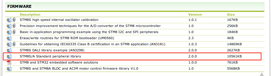
Click here to get this SW Example ready to use, inside there is the excel sheet (STM8-Discovery-TIM4)
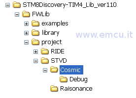
The project was tested with Cosmic C Compiler, the tree of the project is:
First, is important look the clock tree that is show below.
It is important select the clock source that you want to use in your application (default is HSI, RC osc. at 16Mhz).
In my application I'm using HSE clock source.
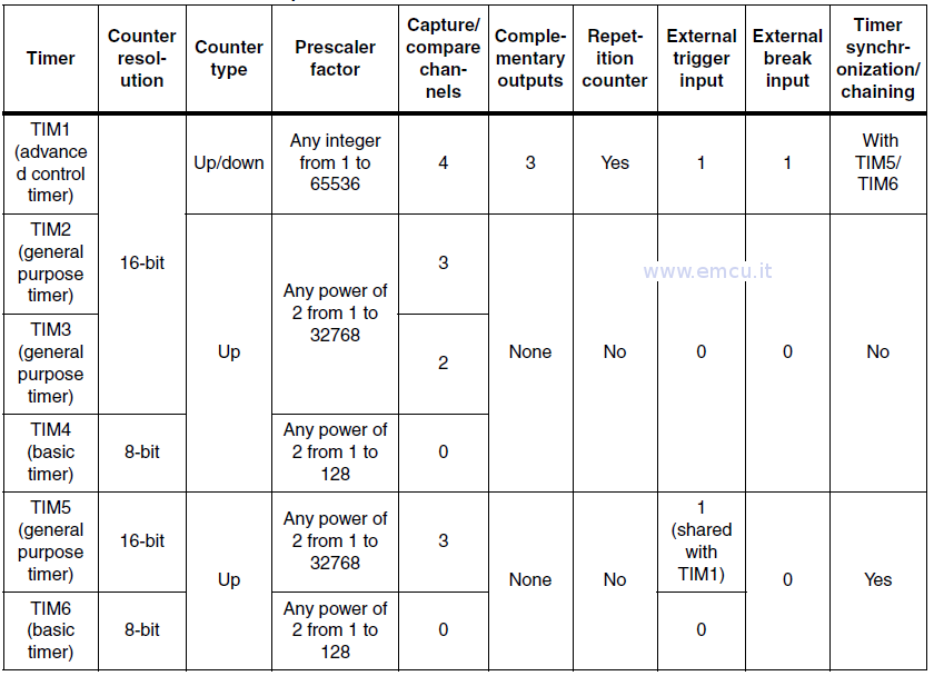
Second, is a good idea see the TIMERs specification, see below.
I'm using TIM4 that is a basic timer and that has a prescaler selectable from 1 to128.
The steps are: 2, 4, 8, 16, 32, 64, 128.
From the RM0016: REFERENCE MANUALS is here, I have develop an excel sheet for calculate the values of:
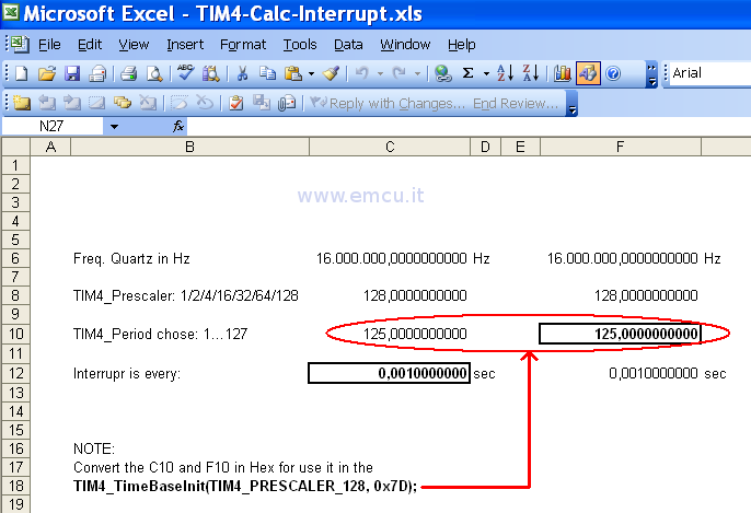
In the BOLD box you see the result of the calculation.
You have two possibility.
My goal is to get 1mS interrupt, so I used the F column.
The Freq is 16Mhz the interrupt time is 1mS so I chose 128 for prescaler and 125 is the result of calculation.
125 is the TIM4_Period.
The implementation of the software was very easy because I used the STM8 Library.
The step are:

All the work is does inside the TIM4 Interrupt routine, see below.
The steps are: 2, 4, 8, 16, 32, 64, 128.
From the RM0016: REFERENCE MANUALS is here, I have develop an excel sheet for calculate the values of:
TIM4_Prescaler
TIM4_Period
see belowTIM4_Period
In the BOLD box you see the result of the calculation.
You have two possibility.
In C column, you have the possibility to insert:
Freq.
TIM4_Prescaler
TIM4_Period
TIM4_Prescaler
TIM4_Period
and the result is the time of interrupt.
In F column, you have the possibility to insert:
In F column, you have the possibility to insert:
Freq.
TIM4_Prescaler
Interrupt
TIM4_Prescaler
Interrupt
and the result is the TIM4_Period.
My goal is to get 1mS interrupt, so I used the F column.
The Freq is 16Mhz the interrupt time is 1mS so I chose 128 for prescaler and 125 is the result of calculation.
125 is the TIM4_Period.
The implementation of the software was very easy because I used the STM8 Library.
The step are:
configure the HSE clock source
configure TIM4
configure GPIOD pin_0 for drive the led that is present on STM8S Discovery
enable interrupts
NOTE: the GPIO pin_7 is not used in this example
see below.configure TIM4
configure GPIOD pin_0 for drive the led that is present on STM8S Discovery
enable interrupts
NOTE: the GPIO pin_7 is not used in this example
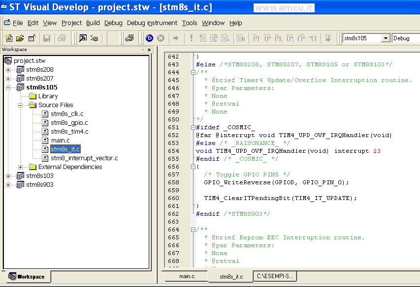
All the work is does inside the TIM4 Interrupt routine, see below.
Line n.658 changes the status of the LED.
Line n.660 reset the Interrupt.
See below.Line n.660 reset the Interrupt.
LINK: